Home alarm with telephone notification: do it yourself. The best wireless GSM alarm system for home
GSM alarm system - blocker
The proposed scheme for blocking a car engine using a cell phone is simple and does not require large expenses.
To do this, you will need any cell phone with a new SIM card, a phone charger from the car’s on-board network, a small number of radio components for the switch unit and a button. All this can be purchased at any radio market.
The cell phone is put in /vibrator/ mode and leads are drawn from the vibrator to the outside, for which the phone must be disassembled, the vibrator itself removed, and the ends removed, determining the polarity (it is advisable to install a connector). To eliminate the function of turning off the vibrator when charging the phone, you need to charge the battery directly, for which a connection is made from the battery connection contacts or a shunt is installed.
A new SIM card must be installed in the phone to eliminate false positives, and only you should know the number via sms ” messages the circuit does not respond.
When you dial a phone number in the car, the standby mode will work and the indicator light will light up; after pressing the brake pedal, the engine will be locked. The unlock button is installed in a secret place in the car, out of sight; unlocking is carried out when the ignition is on by briefly pressing the button.
The lock indicator is displayed on the free peephole of the dashboard; if available or installed additionally, it is best to connect to the right turn indicator; with this connection, the car will immediately indicate a right turn after the lock is activated, and the turn indicator on the panel (in some cases with sound) will indicate the fact that the blocking was triggered is only natural for you.
The switch block is assembled according to the “block diagram”, temporary chain R 1, C 1 is selected so that K1 switches approximately on the 5th ring in the phone, keep in mind that if you redial quickly, the switch will occur earlier because The capacitor will not completely discharge.
The phone is installed in a secret but accessible place, because if the battery is disconnected, it will turn off after a few days, do not forget to turn it on. R 5 is selected in such a way that the phone battery does not heat up, about 30 Ohms.
The switch's power is connected to the ignition switch through a fuse or to a point that already has a low-current fuse. The blocking relay is installed separately and opens the ignition circuit or other devices responsible for engine operation; in operating condition, the relay is turned on.
For convenience, set the number on your phone for speed dialing with one button, and also remember or write down the number in case it is not possible to call from your phone.
To enable the alert function, use the “alert scheme” scheme. Configure the phone in the car to call with one button, to your number, carefully solder the “call” pin to this button, and the “hang up” pin to the hang up button (identify and solder to the connector of the button matrix). Connect the relay to + siren. If the car does not have an alarm system, connect to the door limit switches, changing the polarity; in the case of guarding a garage or apartment, also use a limit switch or reed switch. On your phone, enter this number as an “alarm” and set a separate ringtone. If you answer an “alarm” call, you can listen to what is happening at the facility and take the necessary measures.
If you have one button to hang up and turn off your phone, connect only the call.
Once every 4 months, top up your balance a little so that your number is not blocked.
There is also the possibility of detecting the location of the vehicle because it will contain a cell phone.

GSM alarm system for garage
GSM alarm system for garage The easiest way to protect a garage and other objects is to use an old, unnecessary cell phone, of almost any model.
To do this, you need to set up your phone to dial your number with one button, for example “2”, and turn off the ringer and vibrator. Next, you need to carefully disassemble the phone and solder the wires parallel to the “2” button in a convenient place; it is best to solder them to the connector from the button matrix (determine with a tester). To charge the phone, use a standard charger for this phone, adding a diode and a resistor of about 30 ohms.
For a telephone with an end call and a power off on one button, use diagram 1 with a normally closed reed switch, this is important.
For a phone with separate end call and switch off, use scheme 2 and a reed switch with three contacts; in the phone, solder another wire to the end call button, one of the wires will be common.
Place your cell phone and charger in a hidden, safe place. Install a reed switch on the jamb and a magnet on the door or gate. Install the switch in a secret place or camouflage it as a light switch.
Limit switches can be used instead of reed switches, but they are not reliable in a wet environment.
Before leaving, turn on the alarm and close the door; if the alarm is assembled according to scheme 1, a call may come in, just answer it. After entering, turn off the alarm and also answer the call if it comes. This might be useful as a sanity check. If the alarm system is assembled according to scheme 2, calls do not have time to arrive.
The scheme has a significant drawback: if the gate is closed immediately after penetration, the alarm will not work. Therefore, use a simple device (see figure) on which the reed switch magnet is installed.

It works as follows: before leaving the garage, lift the bar with the magnet up and rest it on the flag; when you close the gate, the magnet will rest against the housing with the reed switch and move back, the flag will lower. If you open the gate, the magnet will also lower, respectively, if you now close the gate, the reed switch will not work. It is advisable to install axial springs on the axis of the bar and flag.
The advantage of this solution is that the alarm works during a power outage, which often happens in garages.
Don’t forget to check the alarm, lift the magnet before leaving, and top up your account a little every four months so that you don’t get disconnected.
Annunciator based on an old GSM cell phone (Kalmykov Boris)
The device was used on a car, in conjunction with a volumetric security alarm sensor (not discussed here). The simplest option was created on the basis of the NOKIA 3310 phone (Figure 1), but any one with the abbreviated dialing function can be used by long pressing one button. Below we will discuss the use of other cell phones, with a different operating logic.
From the very beginning I will say that the cell phone requires modification: several wires (depending on the chosen circuit) are soldered to the keyboard. Be careful.
For NOKIA 3310, on any digit of the abbreviated dial, you “enter” the “owner” number (in the diagram there is a “Favorite button”), turn off the call beeper in the phone (for privacy) and solder the wires from the circuit (the vibrator must be turned off).

The alarm signal is released from the button that is triggered when the car interior door is opened (S1) or the “dry” contacts of the Volume Sensor (S2).
The circuit works this way: when the doors are opened or a foreign object appears in the controlled area, the IC timer (NE555) generates a pulse of at least 1.5 seconds. The “Pressing” of the short dial button “favorite button” is simulated and the call to the “owner” cell phone is made. Based on the number displayed on the “owner’s” mobile screen, he decides whether or not to run to the car and with what “object.” You can “answer” a call and hear who or what is on the microphone at the far end. Since the circuit implements auto-pickup, if you wish, you can call the protected facility and listen to what is happening there.
The element base used does not contain
The logic of the work is as follows:
scarce components. The timers have a domestic analogue K1006VI1. For galvanic isolation of the created unit and the cell phone, any optocouplers can be used. When using only normally open sensor contacts, elements: R1, VT1, S2 can be excluded.
It is possible, with further refinement of this circuit, to order the “object” to execute a command: detonate the squib, turn off the engine, etc. (I'll talk about this below).
For phones with speed dialing with 2 buttons, that is, we press the speed dial button and then the call button, the circuit solution shown in Figure 2 is suitable. A further improvement of the circuit by introducing a motor blocking unit is shown here. An approximate version of the resulting diagram looks like this:

The logic of the work is as follows:
When you call this mobile phone (in a car), the middle timer goes off, and then the bottom one. The output pulse is about 10-15 seconds. If, after the first dialing, you “fight back” and dial the same number again, then there is a simultaneous presence of output pulses on the middle and lower timers. This fact is recorded by the “wiring “AND”” circuit, made on diodes in the base circuit of transistor VT2. As a result, the thyristor opens and holds “0” at output 9. Any blocking can be started from it (Relays, etc.). About “triggering” » blocking is indicated by LED1.
The lock is reset by briefly pressing button S2.
The devices were tested on cars belonging to me and my friends; they were used in the summer when parking on the street, near the house. The unit was powered from an autonomous source - a small-sized battery of a computer backup power supply.
The appearance of the two resulting devices using Siemens C25 and C35 is presented in the photographs.

The good news is that the “unfashionable” mobile phone, which has been lying on the shelf for a long time, is again in service worthy of respect. Yes, the spirit of the radio amateur in us will not dry out!
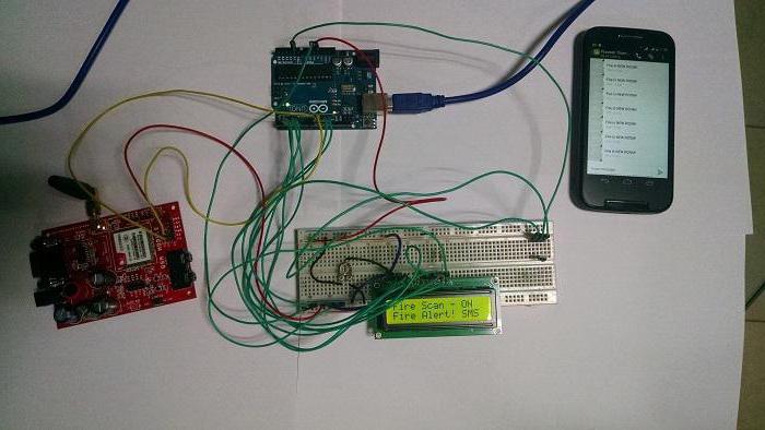
Alarm based on a cheap cell phone (without microcontrollers and processors) (gsm-guard.net)
Operating principle of the alarm
After opening the contacts of the security sensor (limit switch or reed switch), the mobile phone cyclically dials the last number dialed on it by closing the contact pair of the “Call” button using an electronic relay.
The schematic diagram of the device is shown in Fig. 1. The device consists of three functionally complete units: voltage stabilizers with a charger (DA1, DA2, DA3, VT1, VT2), a logical control unit for closing the “Call” button (DD1, DD2, VT4) and an activation unit (DD3, DD4, VT5, VT6).

The charger made on the DA1 stabilizer provides charging of a sealed lead acid battery GB1 batteries with a voltage of 6 V, a capacity of 4 Ah (RB640E, RB640BS - made in China, widely available).
After supplying a supply voltage of 12 V (this supply voltage is selected to allow the device to be used in both stationary and automotive versions without recalculating the circuit elements, in the stationary version it is possible to power the device from a voltage source of 10...30 V with the appropriate selection of relay K1 and recalculation of resistors R1-R3), relay K1 is activated and, with its contacts K1.1, connects the battery to the charger. Charging current begins to flow through resistors R9 and R10. If it exceeds the value of 0.1 C (0.4 A for the specified battery), the voltage across resistor R8 will reach 0.6 V. The opened transistor VT2 shunts resistors R6 and R7, which leads to a decrease in the voltage at the output of the charger and limitation of the charging current at the required level. At the same time, the voltage on resistors R9 and R10 opens transistor VT1, LED HL2 turns on, indicating that the battery is charging. As charging progresses, the voltage on the battery increases and when the charging current decreases to less than 0.02 C (80 mA), transistor VT1 closes and the LED goes out, which indicates the end of charging. In this state, the battery can be connected to the device indefinitely. The HL1 LED indicates that the device is connected to the network. Relay contacts K1.2 eliminate the influence of device elements on the battery charging mode, because The common wire of the device nodes, when powered from the network, is connected to the battery charging current limiting node (transistor VT2 and resistors R8-R12) and the device nodes are thus not in the battery charging circuit. The HL3 LED indicates the “Backup power supply” state. It turns on when the mains voltage is lost and a battery is connected to the device.
The DA2 stabilizer is necessary to bring the input voltage (12 V) to the battery voltage level (6 V) and provides power to the entire device. Stabilizer DA3 DA3 powers (3.6 V) mobile phone transmitter.
The logical control unit for closing the "Call" button of the telephone provides the necessary time delay when leaving the room, sequential double actuation of the electronic switch, leading to the closing of the "Call" button of the telephone (the first closing of the button calls the number from the phone's memory, the second - calling it) and a cyclic algorithm call in case the phone receiving the call is busy.
The device is activated to open the contacts. As soon as the contacts SF1 (door sensor) open (this will happen when the door is opened), the device goes into alarm mode - it starts calling the previously entered number, repeating a series of calls with a period of approximately 1 minute. until the activation node is powered off. At the moment power is supplied to the control unit by closing the “Call” button of the telephone through the contacts of relay K3.1, charging of capacitor C6 begins through resistor R17. This charging takes approximately 20 seconds. During this time, the RS trigger on elements DD1.3, DD1.4 is forcibly held in the zero state (the output of element DD1.3 is low) and does not respond to changes in the level at the lower input of element DD1.4, and therefore to the state door sensor SF1. During this time you must leave the premises. The output level of the trigger is inverted by transistor VT3 and a high level is supplied to the lower input of the element DD1.1 and to the R input of the counter DD2. As a result, counter DD2 is kept in the zero state, and the multivibrator on elements DD1.1 and DD1.2 is blocked and does not generate pulses. In this state, all outputs of counter DD2 will have a low level, transistor VT4 is closed, relay K2 is de-energized and its contacts are open. This state of the device corresponds to standby mode.
Let's assume that while the device is in standby mode, the door is opened. The contacts of the SF1 sensor opened and, through resistor R16, a high level entered the lower input of element DD1.4. Trigger DD1.3, DD1.4 switches to the single state, the voltage at the collector of transistor VT3 decreases to almost zero. In this case, the multivibrator is activated on elements DD1.1, DD1.2 and pulses are sent to the input C of counter DD2. The pulse repetition period is 7 s. At the end of 1 and 3 multivibrator pulses, a high level appears alternately at outputs 1 and 3 of the counter, respectively, which leads to the opening of transistor VT4 and the operation of relay K2, which with its contacts K2.1 twice, with an interval of 14 s. closes the contacts of the "Call" button of the mobile phone. At the end of the fourth pulse at input C of the counter, diodes VD4, VD5 close, which leads to the closing of transistor VT4. At the end of the eleventh and thirteenth pulses at input C of the meter, the contacts of the “Call” button of the telephone are closed twice again, etc., i.e. The button closes cyclically every 10 multivibrator pulses.
The HL4 LED indicates pressing the phone's "Call" button (in principle, it is necessary at the stage of setting up the device - it can be eliminated in the future).
The activation unit is designed to control relay K3 using the reed sensor SF2. The relay contacts close and open each time the sensor contacts are closed (each time the magnetic key fob is brought to the installation site of the SF2 reed switch). The node controls a logical node that closes the “Call” button of the telephone when entering and leaving the room, i.e. when arming and disarming. This ensures the supply or removal of supply voltage (6 V) to the logical control unit of the phone's "Call" button.
The activation unit consists of a single-vibrator on a DD3.1 trigger, a DD3.2 trigger, a VT5 transistor and a K3 relay. After power is supplied to the device, relay K3 is de-energized, contacts K3.1 are open. When the contacts of the reed switch SF2 are closed, the contact bounce pulse triggers the monovibrator and generates a positive pulse lasting about 0.5 s. At the same time, a high level appears at the output of trigger DD3.2, transistor VT5 opens, relay K3 is activated and its contacts K3.1 supplies power to the logical node. The next time the contacts of the reed switch SF2 are closed, the single-vibrator again produces a single pulse with a duration of about 0.5 s, which leads to the fact that the DD3.2 trigger changes its state - a low level appears at the trigger output, the VT5 transistor closes, the K3 relay is de-energized and the K3 contacts. 1 break the power supply circuit to the logical node for controlling the “Call” button of the phone. Thus, each closure of the contacts of the reed switch SF2 changes the state of relay K3, the contacts of K3.1 of which, in turn, supply or turn off power to the logical node.
The intermittent signal generator on the DD4 chip is used for half-second audio notification of activation - deactivation modes, i.e. Every time you briefly bring the key fob to the installation site of the SF2 reed switch, an intermittent sound signal is heard. The generator consists of two interconnected multivibrators, one of which, based on elements DD4.3 and DD4.4, generates pulse trains with a repetition frequency of about 2 Hz at the output, and the second, based on elements DD4.1 and DD4.2, generates filling pulses with a frequency of about 1 kHz. The generator is started by applying a high-level control voltage from the output of the monostable on the trigger DD3.1 to the lower input of element DD4.3. The glow of the HL5 LED additionally signals activation.
The general operating algorithm of the system is as follows:
1. When leaving the room, briefly bring the magnetic key fob to the installation site of the SF2 reed switch. A half-second beep and the glow of the HL5 LED indicate that the system is armed;
2. You must leave the room within approximately 20 seconds, during this time the system will not respond to opening or closing the door;
3. If the door to the room is opened unauthorized, after about 25 s. (this time depends both on the frequency of multivibrator pulses on elements DD1.1 and DD1.2, and on the dialing speed determined by the GSM network itself) dialing occurs at the phone number dialed last on the mobile phone - transmitter;
4. Continuous dialing to the subscriber occurs for approximately 45...50 s., at this time the receiver phone rings, then after 50...60 s. After a pause, a repeated forty-five-second dialing occurs, etc. cyclically;
5. After receiving a notification about a break-in by the receiver phone, by pressing the “Call” button on it, it is possible to listen to the protected object within 45… 50 s.;
6. To unlock the system, after opening the door for about 20 seconds (this time depends on the frequency of the multivibrator pulses on elements DD1.1 and DD1.2), briefly bring the magnetic key fob to the reed switch SF2. At the same time, a short beep sounds and the HL5 LED goes out.
The device uses RES22 relays, RF passport 4.500.129 (K1); RES 49, passport RS 4.569.026 or RS 4.569.032 (K2, K3). You can use other relays with the corresponding number of contact groups. K1 - for response voltage 12 V; K2, K3 - for an operating voltage of 4...6 V. Diodes VD1, VD2 are replaceable with any that can withstand a current twice the charging current (400 mA).
The transistors indicated in the diagram can be replaced with any of the KT 315 (VT1, VT3, VT6), KT 3102 (VT2), KT 815 (VT4, VT5) series.
The BF1 telephone capsule is used from the same telephone used in the device. It must be carefully removed from the phone body. Stabilizers DA1, DA2, DA3 are placed on three needle-shaped heat sinks measuring 45 x 20 mm.
All parts, with the exception of the door sensor, reed switch of the activation unit, telephone capsule and LEDs, are mounted on a printed circuit board made of single-sided foil fiberglass 1.5 mm thick, dimensions 125 mm x 60 mm.
The phone is connected to the printed circuit board with two pairs of wires. One pair is soldered directly to the printed conductors going to the contacts of the "Call" button, the second - to the printed conductors of the phone's power supply. In addition, a microphone is carried out from the telephone by a shielded wire, which is used to listen to the room.
A properly assembled device requires minimal adjustment.
With the battery disconnected, power is supplied and, by selecting resistor R6, the voltage at the charger output is set to 6.75 V. Instead of the battery, a 10 Ohm resistor with a power of 2 W is briefly connected and the current flowing through it is measured. It should not exceed 0.4 ... 0.45 A. The voltage of 6 V and 3.6 V is measured at the output of stabilizers DA2 and DAZ, respectively; in extreme cases, resistors R15 and R26 are selected to adjust these values.
To check the functionality of the entire device, turn on the transmitter telephone and dial the telephone number to which you will need to call.
The security alarm board, telephone and battery are installed in a common durable plastic case. LEDs (5 pieces) are located on the front panel of the case (for secrecy, LEDs do not need to be installed). The SF2 reed switch can be located both inside the housing and outside in a hidden place. The SF1 sensor is placed on the door frame if the alarm is used indoors, or a standard door switch is used if it is a car. In the auto version, it is advisable to use an existing car security alarm in conjunction with the described alarm system, applying a high level when the existing alarm is triggered to the lower input of element DD1.4 of the logical unit for controlling the closure of the phone's "Call" button (in this case, the SF1 sensor and resistor R16 are turned off).
Also, a microphone and a telephone capsule, removed from the phone body, are fixed inside the case. Two small holes are drilled in the case and a microphone and telephone capsule are glued from the inside to these holes. 12 V power is supplied to the unit through a connector located on the side surface of the case. In the author's version, two nodes are added to the basic version of the security alarm (Fig. 1): a motion sensor (not shown in the diagram) and a speech module (Fig. 2).

The digital output of the motion sensor is connected to the lower input of the DD1.4 element (in this case, the SF1 sensor and resistor R16 are disconnected). When movement occurs in the sensor's coverage area, a high level appears at the RS trigger input, which leads to the launch of the multivibrator and the logic node counter.
The speech module (Fig. 2) is designed to pronounce the phrase “The system is activated, please leave the room” when the system is activated (by bringing the key fob to the reed switch when leaving the room). However, you can record any other phrase for playback if you wish. The speech module consists of a speech recording and playback chip DD1 and a power amplifier DA1. The technique for recording speech into the ISD 1416P chip is presented in. When leaving the room, bringing the magnetic key fob to the reed switch SF2, a high level appears at pin 12 of the DD3 trigger. In this case, a low level appears at pin 24 DD1 of the speech module, which leads to the reproduction of the voice phrase previously recorded in the DD1 chip.
The motion sensor and speech module are also installed in the common body of the system.
The type of printed circuit board is shown in Fig. 3 and Fig. 4.

Connection points are shown in Fig. 5.

This article provides an opportunity to obtain information about the methods by which autonomous GSM alarms are assembled, installed and maintained. Each device of this type almost always operates on the basis of a special module. In fact, this is the same mobile phone, but without keys, screen and body. Instead of these devices, connectors for sensors are attached to the main board. GSM modules are provided by such leading corporations in the mobile phone manufacturing market as Siemens and Motorola.
A large number of high-quality professional security systems from foreign manufacturers are being developed, the purchase of which is limited for a wide range of consumers. There are practically no descriptions of the principles of assembly of such devices.
DIY GSM module
Understanding the basic principles of operation of this type of alarm is necessary when starting to equip any facility with a GSM installation. The devices consist of appropriate outputs for sirens and detector sensors. When an alarm situation occurs, the device can be programmed to perform certain actions. Such control units are capable of processing voice messages, sending SMS notifications to owners of protected premises or corresponding alerts to security systems managed by law enforcement officers.
In addition to the above, GSM alarms are capable of activating light warning systems, sound sirens, and sending mass messages to several subscribers simultaneously. You need to decide on the components that you plan to install. The quality of operation and signaling capabilities will depend only on the developer.

Preparing for installation
As an example, we consider an assembled and configured homemade GSM (burglar alarm) in an ordinary apartment in a multi-story building. The first step is to select all the necessary sensors. The ability to control hired workers, such as nannies, is often in demand. If you plan to develop a GSM alarm system for the protection of industrial or commercial facilities, in addition to a noise recognition device, you will also need a motion detector and devices sensitive to impacts and glass breakage, as well as sensors for monitoring smoke and interaction with magnets.
Sensitive elements transmit a signal to the GSM module if the entrance doors are opened, windows are damaged, or an attempt is made to enter the protected premises in any other way. Then, depending on the settings, the siren is activated, alerts are sent to programmed numbers, the lighting equipment is turned on, or several functions are performed simultaneously. If you assembled the GSM alarm yourself and installed it correctly, you must activate it every time before leaving the territory of the protected facility.

Glass break sensors
At this stage, you have to make a choice between reliability and aesthetic design. When you select the first property, the appearance of the window can change significantly. After installing the sensitive device, a transparent mesh will appear on the glass, which can be seen if you look closely.
If the solid surface of the glass is damaged, the sensor transmits a signal to the control unit, which will instantly begin performing all of the above possible actions. In order not to spoil the appearance of the surface with the mesh, new internal audio detectors are used for installation, which are directed to the windows. Such devices are characterized by unmistakable discrimination between the sound of breaking glass and any other objects.
Smoke sensors
Setting up a GSM alarm using smoke detection devices will always be relevant for any type of protected objects. It is advisable to install additional devices to neutralize fire. When creating an alarm system with your own hands, you can add a huge number of different devices to the system. You need to understand that the number of connectors on a GSM module is limited, and the choice should always be made wisely.
Device distribution
In a residential area, sensors for detecting movement can be installed in the kitchen, rooms or hallway. The actions of any person who tries to enter the building without the knowledge of the owner of the apartment or the responsible employee of the enterprise will be immediately detected by special security devices.
A GSM alarm installed by yourself always requires choosing a location for the control unit and antenna. If integrated, the detector should be placed at the minimum possible distance from the window. If the antenna is portable, it will have to be installed in the area of best reception of the signal sent from the main station. The control unit can be installed in the most convenient place. Installation in areas of the wall inaccessible to small children is recommended.

Using an old mobile phone
The development technology is very simple. On button 1 of the mobile phone there is a tape recorder icon. If you hold for a long time, you can call the number specified in advance. GSM alarm systems work on this principle.
The instructions for installing a mobile device are not complicated. The processor scans the state of the button. To close the contacts, some low-power optocoupler is suitable.
The output pulse is applied to the middle contact, and the signal level is checked. Galvanic discharge from external elements is in excellent agreement with the telephone circuits. The optocoupler is soldered to the contacts with short conductors and secured to the mobile phone.
A small remote button is used to perform the function of key 1. When a pulse is received, a call is made. The subscriber can listen to everything that happens in the room by pressing the call button. An ordinary charger is suitable for powering an integrated mobile phone.

GSM - security alarm with installed interface circuit
This method makes it possible to use a signal that is supplied to sound warning devices. The output of the comparator LM311 will open some time after the capacitor reaches 7 Volts. After the comparator starts operating, current is supplied from the resistor to the optocoupler. This is how the call is made.
Using a resistor, you can adjust the duration of the delay for activating the comparator. This is designed to prevent false calls during short-term alarm activation. The interface circuit is placed on a small board and installed together with the charger in one case.
Connecting the secret
Situations may arise when the password is scanned, the key fob with keys is stolen from the owner, or they are hacked so that the GSM alarm never goes off. Anyone can create a so-called secret with their own hands. It's easy to connect. The device contact for powering the LED is displayed on the interface circuit. If, after starting the engine, while the capacitor is gaining power, you do not press the secret button, a call is made.
Complete handsfree
This technology is only used for car alarm circuits. A complete HF system can be used instead of a charger. Such devices provide power and mount for telephones, improved communication quality due to an antenna, and two-way speakerphone communication.
For Nokia, the original CARK91 system can be used. will be improved thanks to such a device. Added auto-reply feature. When the volume is set to minimum, everything will be heard clearly. The microphone is installed in the cabin. The system itself can be placed in the fire extinguisher compartment.

Conclusion
Finally, it’s worth adding a few words about what a do-it-yourself GSM alarm system should look like. The circuit necessarily includes all of the above sensors. Detectors and sirens must be correctly connected to the software module ports.
The system must be installed at home before renovation work is completed. In another situation, you should resort to the help of specialists so as not to create additional problems for yourself. Afterwards there is always a lot of construction waste, dirt and dust left in the living space.
A distinctive feature of wireless alarm systems is that tracking sensors communicate with the central unit via the GSM network. To operate, a SIM card of the selected operator is installed into it. GSM equipment is a home alarm with telephone notification. After switching on, the central unit finds all installed sensors and begins taking readings. If one of the sensors is triggered by movement or another indicator of a violation, an alarm is sent to the center and a siren sounds, and a message is sent to the owner’s mobile phone.
The device is programmed so that the phone beeps until it receives a signal. The mode of the central unit is set by the owner, each zone is programmed for a specific signal, and when it arrives, it is determined in which sector the tracking sensor is triggered. The equipment is installed in various areas of production, used in offices, private buildings, GSM installed
Benefits of a wireless tracking system
The device has many advantages over conventional alarms:
- the wireless system easily works in houses and separate premises where there is no telephone connection or electricity;
- there is no subscription fee for a quick response and the arrival of a security detail, the signal instantly notifies the owner, and he acts at his own discretion;
- The system design provides protection against false responses to the movement of insects and animals, which is very valuable compared to conventional equipment.
Components
The device is available in a standard or extended version. The standard scheme is equipped as follows:
- tracking sensor;
- alarm sensor for opening a door or window;
- siren device;
- set of key rings.
The standard equipment is expanded by an additional number of sensors, and additional notification devices are added gradually after installation of the main equipment.
Review of the model "Guardian Falcon Prof"
A set of high quality devices is used in the wireless "Guardian". GSM home alarm is a representative of a new generation of systems to which various types of sensors can be easily connected. It is possible to install a microphone to listen to the protected area. Alarm messages and dialing are sent to three telephone numbers. For notification, the central point contacts 9 wireless notification zones, round-the-clock operation is provided for

SMS messages in Russian are transmitted by a home alarm system with notification by telephone. "Guardian" is characterized by a high-capacity battery, which allows you to not recharge the system for up to three days. Programming the system is done from the remote control or by telephone message, which saves telephone costs. If the signal level at the central point loses intensity, then the owner’s phone receives a message about the use of a cellular wave suppression system in case of a hacking attempt.
To determine the operating mode, a wired free-standing beacon is used, which notifies random visitors about the security of the premises or object. If there are places on the territory where the radio signal is blocked for various reasons, then provision is made for connecting wired devices to a common center. The specified GSM alarm system for the home works as a reliable and functional system.
Alarm Falcon Eyei-Touch
The equipment belongs to standard wireless devices. Sold with an installed program, expansion of the field of activity is provided through the installation of additional reading sensors. Wireless GSM alarm system for home and garden is distinguished by the fact that up to 50 sensors and about a dozen remote controls are connected to it, which are easy to operate. For alarm messages, 5 telephone numbers are provided, from which the operation of the device can be easily reprogrammed. A notification to the owner comes when the batteries are low, the capacity of which allows them to work autonomously for 5 hours.
Falcon Eye Simple security system
The model is intended for installation in residential buildings. The successful design look easily fits into the most sophisticated interiors. The standard set of components is the same as in the Strazh system. GSM home alarm systems are also expandable if there is a need to increase the surveillance area. Works with a large number of information readers, has a voice message, and listens to the controlled area. The communicator is easy to maintain and control; programming is carried out by telephone message. The battery lasts about 8-9 hours.

Signal XM - reliable security
The text in the message is transmitted in English, which is not always convenient. If the ambient temperature drops to -5ºС, then the capacity of the batteries in the sensors may decrease. It has an affordable price and good functionality. A type of alarm system used for installation in a garage is called Signal XQ. This device has several types of sensors that respond to vibration, smoke, and movement. It is possible to receive a message once a day by phone or every time upon request.
Alarm System SGA-G10A Android
It is ideal for installation in premises for various purposes. Wireless GSM alarm system for home is a ready-made kit for use in a garage, apartment, house, or office. All devices are adjusted, and the kit can be easily installed by a person without prior preparation, which is an excellent way to save money on inviting a specialist.
The alarm box has a successful design solution, allowing its installation in various styles of room decoration. Touch elements are provided for control, and the technical parameters of the system are displayed on the screen for viewing. The work is simplified to pressing one button, increasing the number of sensors is much easier than in other systems. Today this is the best GSM alarm system for the home. User reviews are positive.
It is allowed to connect up to a hundred wireless surveillance zones and two wired ones to the central unit, the number of numbers for voice notification is 5 pieces, SMS messages are 3 pieces. The intruder is detected at a distance of up to 12 meters, the increased viewing angle of the zone is 110º. The alarm operates with sensors at a frequency of 433 MHz. Sensors are used of various types: opening of an opening, movement, glass breaking, vibration.
The activation of the siren can be heard at a distance of several hundred meters; if there are many objects, then you can see which one is in danger on the screen (mini-display), and the response time is also displayed there. The system operates in two telephone communication standards, works with all operators, and is connected, at the owner’s request, to a landline telephone.

It is possible to program commands from the phone; now there is no need to remember complex digital and alphabetic codes, operations are carried out by pressing one button. The name of the security zones from the number is renamed according to the name of the premises, for example, kitchen, bedroom, etc.
Security alarm kit 30 A
It appeared on the market recently and has already collected many positive reviews, thanks to its excellent quality at a relatively low price. The device is housed in a plastic case with an opening lid, and the keyboard is backlit. Built in with a well designed interface. A modern device of the latest generation not only helps the owner from encroaching on the territory, but also speaks of the luxury of home ownership.
A call is made with a voice message to 6 phone numbers. A home alarm with telephone alert sends a message to three numbers if the sensor is triggered. Up to one hundred information collectors are connected to the system, which are placed on all possible variations of penetration, for example, a door, a window, a safe, or collapsible enclosing structures. The system settings, the operating status of the alarm are monitored on the screen, the alarm unit is used as a telephone for calling friends and acquaintances.
Selection criteria and price
Having considered the features and technical characteristics of all systems, they choose the optimal one for installation in the selected room or in an open area. For large areas, systems with the ability to connect a large number of sensors are used, but such kits are more expensive. Small economical premises and garages are protected by small functional systems to reduce costs due to a small number of sensors.
Price is often a determining factor in purchasing equipment, but for wireless alarms it is one of the advantages. On average, the cost of a standard set is about 7-11 thousand rubles, which makes it affordable for the general population. This is a low price to pay for peace of mind for your property, with the condition of prompt notification in connection with violations.

A home alarm with telephone notification is selected taking into account the name of the manufacturer and the country of production. Chinese lightweight models are equipped with a casing made of low-quality plastic, batteries are often not included in the package, and sometimes there is no warranty for the equipment. Such systems are cheap, but the quality leaves much to be desired.
Security equipment is selected taking into account functionality; the best set is a GSM home alarm system; it instantly transmits a signal to the owner’s phone and allows him to respond very effectively. If the system is equipped with a siren, then strangers will not want to be in the apartment even after a successful break-in.
When choosing, take into account the ability to connect wired systems, battery capacity, and the presence of a convenient screen with a clear interface. Based on this data, the optimal solution for protecting the facility is selected. Additional functions included in the kit are important, such as temperature control and network voltage.
Connection instructions
GSM home security alarms are easy to install and will not take much time even for an untrained user:
- selecting a location for installing the central control unit;
- tracking sensors are mounted in the places of their monitoring purpose, preferably at an equal distance from the central unit;
- infrared sensors are placed on the line of possible human passage, at a height of no less than 2 m from the floor surface, the angle of inclination is no more than a right angle;
- sensor motion detection range is about 8 meters, inspection angle is no more than 110º;
- opening sensors are installed on a fixed frame, a magnet is placed on a movable sash, a gap between them is maintained of no more than 1 cm;

Making an alarm with your own hands
Craftsmen create wireless alerts in the event of dangerous situations on their phones themselves, which helps save money. For work, purchase materials and tools:
- mobile phone with the ability to quickly dial the selected number;
- sensor for reading sounds from the surrounding space in the form of a microphone;
- push-button sensor for opening an opening (window or door);
- 12V acid-gel battery (you can take a battery with a larger capacity, which will increase the battery life in the absence of electricity);
- Accumulator charging;
- soldering iron, solder, pieces of wire.
A home alarm with telephone notification works on the principle of closing a contact on the cell of one of the numbers in the phone, which is programmed to quickly dial the owner’s number.
Procedure
A number is selected on the keyboard, and the ability to quickly dial is configured in the phone functions. To avoid surprises in the future, speed dialing is checked when a key is pressed. After this, the back surface of the mobile phone is removed, then the front part with the screen is removed, and the board, protected by a white film, is released for work.
To connect the wiring, two cuts are made under the desired button. After lifting the film, a metal membrane located on the inside becomes visible. This part performs the function of closing two contacts, the midpoint and the ground. The wire is soldered to two contacts; it is advisable to take one so that there are two wires in the winding, this will reduce the number of interference and false calls.
To prevent unexpected short circuits, a small square of insulating tape is glued to the membrane, closing it. If it is planned to eventually return the phone to normal working use, then the membrane is not removed. The cell phone is prepared for operation, and then a home alarm system is installed with telephone notification. It’s not difficult to make such a connection with your own hands; you decide on the option of closing two contacts.
Two microcircuits are used: K561LN2 and K561LA7, this alarm sets the time for the owner to leave the boundaries of the protected object and determines the period for the owner to enter the territory to turn off the alarm. At this time, there is a delay in response to movement and other parameters. A self-designed wireless GSM home alarm system expands its application possibilities by installing additional sensors.
Options for connecting a phone to an alarm system
For one of them, a relay with open contacts is used. The relay coil is connected to the alarm output. If an alarm is triggered, voltage is applied to the winding, the contacts are connected, and the phone button is pressed, sending a call signal to the owner’s phone.
The second method is to connect a bipolar transistor directly to the phone keypad. The output of the transistor is in contact with the common wire, and its collector is connected to the push-button contact. Voltage is supplied to the transistor base through a resistor and the GSM home alarm system starts working. Reviews from those who use this scheme indicate its sufficient reliability.
Connecting a telephone using an optocoupler helps create an isolated circuit from a galvanic point of view. An optotron is an electronics device containing a light emitter and a photodetector, enclosed in a common single housing. Both components of the optocoupler do not have common contacts, so the security circuits are powered from different sources without common wires.
All three connection methods are valid when connecting a cell phone to any alarm system. A GSM alarm system can be installed for a home or garage and can be easily connected to car security.

How to ensure uninterrupted power supply
Use a regular device to charge the telephone battery. This is a simple method, but the battery is constantly in full charge mode, and the lithium battery is gradually destroyed.
An ordinary phone battery is used, but for charging a fixed power source voltage of up to 4 volts is used with a permissible load current of 700 to 1000 mA. This power supply allows you to accumulate not the full volume in the battery, but only up to 70-75%.
Another option is to bypass the landline telephone battery and connect to the security system battery, which is up to 12 volts and is constantly recharged. In this case, a current converter or transformer is installed. Before connecting such a device to the phone, be sure to check the output voltage, which should not exceed 3.9-4.0 volts.
A sagacious owner must protect his home, work enterprise, garage, or car from attempted break-in and entry. Wireless alarms help to perform this function reliably, economically, without difficulties and problems.
Security alarms for cottages and homes play a fairly large role in modern life, and, unfortunately, the installation of such systems requires some costs.
However, some alarms are not very complex, do not require complex components and are much cheaper than their counterparts.
Therefore, such systems can be implemented even by radio amateurs. Let's figure out how to make a simple alarm system in the countryside with your own hands.
DIY GSM alarm for home
One of them is a homemade GSM alarm system for a dacha with your own hands from a cell phone. It can perform the main function of alarms of this type - making a call when the alarm is turned on.
 A DIY burglar alarm system consists of several elements, namely:
- Unnecessary mobile phone with a push-button keyboard.
- Sensor such as reed switch and magnet.
- Switch.
- Set of wires.
What tools are needed?
Do-it-yourself GSM security alarm systems for summer cottages are very simple. You don't need professional tools to make them. Will come in handy:
- Soldering iron and skills to work with it.
- Knowledge of electronics.
- Mobile application programming skills may be required.
Scheme
A DIY home alarm system has a circuit where the following components are connected in series:
- Switch.
- Reed switch opening in a magnetic field.
- One of the telephone keypad buttons.

Let's figure out how to make an alarm for your home yourself with notification by phone:

DIY alarm system for a private home works according to the following principle: when the door is opened, the reed switch closes a contact on one of the mobile phone buttons, which is responsible for speed dialing and making a call to the owner’s phone. If you pick up the phone at this moment, you can hear what is happening in the protected area.
How to use the video camera and set up SMS?
The previous system is quite primitive and simply rings when the door is opened. Is it possible to add additional functions, for example, sending SMS, or the ability to take a photo using the phone's built-in camera and send it via MMS? Let's figure out how to make a GSM alarm system for a dacha with a video camera with your own hands.
This is possible, but to create such a system you Mobile application programming skills will be required so that when a button is pressed or an alarm circuit is closed, the phone performs a more complex sequence of actions. Or you can take one of the ready-made applications, which was created by electronics enthusiasts specifically for homemade GSM alarms.
However, this carries some risk from a security point of view, and no one can guarantee you that a homemade home alarm system will work correctly at the right time. For this reason, it will be preferable if you develop the software yourself.
Useful video
Conclusion
A simple DIY alarm system for your dacha and garage is ready. As you can see, it’s quite possible to make one from an old phone. Especially if you have all the skills to do it.
Of course, there are no guarantees that such a device is capable of providing the required level of security; it has very little functionality and is much inferior to professional security systems.
But at the same time, this homemade alarm system for the home can be quite effective, for example, for protecting a garage.
Modern life is unthinkable without security alarms. They come in a wide variety - for example, fireproof or burglar-proof, and vary depending on the installation location and, accordingly, the required functionality. A country house also needs protection and the best option for it is a GSM alarm system.
Nowadays, there are a lot of companies providing alarm installation services, including those with GSM technology. At first it may seem to you that such systems are extremely complex, but in reality this is not the case. The main thing is to understand a few important nuances, after which you can make an alarm on your own, without resorting to outside help. It will cost several times less, moreover, further maintenance of the security system will depend solely on you. In other words, you will carry out preventative measures and troubleshoot problems yourself.
Despite the fact that GSM alarms are installed mainly in garages, they can also be successfully used to protect a home. The simplest security system described in this article can solve many problems and also add confidence in the safety of your property.

To make your own alarm you will need:
- soldering iron and ability to work with it;
- set of wires;
- wire cutters;
- an old mobile phone (necessarily with buttons - modern touchscreen models will not work);
- single-key switch;
- stationery knife;
- insulating tape;
- small magnet;
- Super glue;
- copper and telephone wires;
- a pair of metal clips;
- multimeter;
- minimal knowledge in the field of radio engineering.
After reviewing the list of necessary tools/materials, we conclude: the cost of a homemade alarm system is low. If you strictly follow the instructions below, the security system will last quite a long time.
Do-it-yourself home alarm system - installation work
In essence, a GSM alarm system is an improved mobile phone. She will call your (or any other) number if someone breaks into your house while you are away.
The idea is this: you need to ensure that the phone itself calls the last number dialed from it at the moment when the front door opens. This phone should always be on charge and lying in some box near the outlet. As soon as the door opens, the invisible contacts installed on the awnings will close and thereby trigger a call from the mobile phone - you will receive a call.

Note! For alarm, you can use the cheapest phone. The notorious Nokia 1100 is ideal for this.
First stage. To begin, cut two pieces about 1.5 cm long from metal clips - these will be hinged contacts on the door. Then take the telephone wire, strip the insulation and unravel it into a pair of internal wires. Solder the ends of each of them to the contact paper clips. Fix the contacts themselves on the door using superglue - one on a fixed hinged hinge, the second on a movable one.
Select the position of the contacts so that they close when the door is half open. Attach the other ends of the wires to a multimeter, then test them in a closed state (with the door open) in order to check the circuit.

Second phase. Route the wires to the place where the device will be located, hiding them under the baseboard.
Third stage.

Next, proceed to the phone. It must have a SIM card, a top-up balance, and disabled notifications (such as alarm clock, incoming call, etc.). He must also have the last number dialed to which the call will be made in the event of a hack.

Note! It is very important that the outer contour of the semicircular shape does not close.
Also make sure that the electrical tape does not cover the contact to the end call button.
Fourth stage.

When everything is ready, install the battery (you can throw away the case - it is not needed), using the same electrical tape for fastening (it is important that it is blue). After that, turn on the phone. This may seem impossible to you, because the keyboard is no longer there, but here your ingenuity comes to the rescue: take a metal paper clip, straighten it, making a kind of tweezers, and close the contacts under the right button to end the call.
Once the screen has greeted you and the phone has fully booted up, try shorting the copper wires installed in the previous step. If everything is done correctly, the phone will dial the last number dialed. But if this does not happen, you will have to check all the contacts under the button again and repeat the procedure.
Fifth stage.
All that remains is to install the phone in the designated place. Connect the copper wires coming from the telephone to the contacts leading from the door hinges. Then connect the charger and plug it into a power outlet. That's it, the GSM alarm system has been successfully installed.

Note! For convenience, you can install a toggle switch on one of the long wires to turn the alarm on/off.
As already mentioned, usually such an alarm is installed on the front door. We advise you to attach the contacts to the internal door between the rooms (it will always need to be closed before leaving). If an intruder breaks into the house, he will in any case move from one room to another and, therefore, open the “alarm” door. After this, a subscriber known to you will call your number and you will be informed about the hack.
Having some knowledge of radio technology, such a security system can be improved to make it look more presentable, and a car alarm can also be made based on it.
An important point you need to know
If an intruder enters a house with such an alarm, he will be able to quickly detect it and turn it off. A homemade security system requires a certain time to operate (often a few seconds), that is, to establish a connection with your mobile phone.
An indisputable advantage of such a homemade alarm system is its energy independence. You just need to charge your phone battery in a timely manner using a standard power supply. It is advisable to completely integrate this unit into the electrical network so that the phone is powered by the battery only during power outages.
We also note that today it is more advisable to install a video surveillance system. It has a lot of advantages, but is very expensive, so in most cases people make do with regular GSM alarm systems.