WiFi ESP8266 is a new step in the design of home devices with a wireless interface. ESP8266 "Witty Cloud" is currently the most successful WiFi module for homemade products and smart home
The ESP8266 chipset module is simple and cheap way add functions to your device wireless communication via Wi-Fi.
Use the ESP8266 to control your device remotely or to take sensor readings over the Internet. Connect your gadget to social networks or react to data you receive via API from web services.
There are many varieties in the ESP8266 family of modules. The presented module is ESP-01. Him WiFi antenna is built into the board, and the legs additionally have 2 free-use GPIO ports.
Interaction
The control device communicates with the ESP8266 via UART (Serial port) using a set of AT commands. Therefore, working with the module is trivial for any board with a UART interface: use Arduino, Raspberry Pi, whatever your heart desires.
Working on receiving and transmitting data looks like interacting with a raw TCP socket or a computer’s serial port.
Moreover, the module can be reflashed. You can program and upload firmware through the Arduino IDE, just like when working with Arduino. Response to AT commands is simply a function of the firmware installed at the factory. And you can write your own if the project requires it. Because there are 2 I/O ports on the module general purpose, you can do without a control board at all: just connect the peripherals directly to them.
In order for the Arduino IDE to learn how to flash the ESP8266, just add the directory with the platform configuration to the folder with your sketches.
For a physical connection when flashing the firmware, you will need a USB-UART converter or an Arduino/Iskra board configured in USB bridge mode.
Nutrition
The native voltage of the module is 3.3 volts. His pins not tolerant to 5 volts. If you apply a voltage higher than 3.3 volts to the power, communication, or I/O pin, the module will fail.
Therefore, to transfer data to the module from 5-volt control boards, use to bring the voltage into the acceptable range. A divider of two resistors of the same value (for example, 10 kOhm) is suitable.
No intermediaries are needed to receive data. A 3.3 V signal as it is will be perceived by the control board as a logical unit.
Power the module with an even 3.3 volts. These can be obtained from a separate voltage regulator.
The module consumes 220 mA peak. The voltage regulator used on five-volt Arduino boards for the 3.3V pin may not be enough. Pay attention to the specifications of your board. For example, Arduino Uno and Arduino Leonardo can output no more than 50 mA from the 3.3V pin, so you must use an external regulator with them; and the Iskra Neo can supply up to 800 mA, so it can power the ESP8266 directly from the board.
Pinout
Due to the position of the legs close together in 2 rows, the module cannot be installed on a breadboard. Use a solder breadboard or wires with female connectors to connect to the module pins.
Was warmly received by the Habra community. Despite the fact that it contained little specific information. There was a good reason for this - the NDA we signed to receive the SDK from the solution manufacturer, Espressif. That is why we simply said, “here, there is such a solution.” So that those interested have the opportunity to pay attention.
The other day we (the COOLRF project, don’t forget subscribe to our VKontakte community, if you are not already a member) have received permission from the chip manufacturer to publish information in our articles that was previously subject to the terms of a non-disclosure agreement. Anyone who was interested in the details is welcome under cat.
Typical use cases
The ESP8266 is designed for use in smart sockets, mesh networks, IP cameras, wireless sensors, wearable electronics and so on. In short, the ESP8266 was born to become the brain of the upcoming Internet of Things.There are two options for using the chip: 1) in the form of a UART-WIFI bridge, when an ESP8266-based module is connected to existing solution based on any other microcontroller and controlled by AT commands, ensuring the solution communicates with the Wi-Fi infrastructure; 2) implementing a new solution that uses the ESP8266 chip itself as a control microcontroller.
The first scenario was briefly described in our last article. It is implemented using any of the inexpensive Chinese ESP8266 modules. Well suited for Arduino lovers and those who already have in their hands ready-made schematics and debugged firmware based on something of their own, dearly loved.
The second version of the scenario involves writing custom firmware to control the chip from the inside. IN this moment The firmware must be written for a proprietary compiler. This is basically what the requirements for non-disclosure of information around this decision are related to. In the foreseeable future, the manufacturer plans to switch to using GCC and these restrictions will be lifted.
The scenario of using the chip as a control microcontroller is interesting because it allows you to create devices that are really small and really last a long time on batteries. To work with peripherals, the ESP8266 has all the necessary capabilities.
Key Features
The ESP8266 chip is one of the most highly integrated WiFi solutions available. Inside the chip fit a bunch of everything that in competing solutions is often part of the external trim:As a result, a typical chip harness consists of only a few elements. Fewer elements = less price of components, less cost of soldering, less area of placement, less cost printed circuit board. Which is perfectly confirmed current prices modules based on the hero of our today's review.
All this integrated management is controlled by an extended version of Tensilica’s L106 Diamond series 32-bit processor. What's interesting inside?
- 802.11 b/g/n protocol
- Wi-Fi Direct (P2P), soft-AP
- Integrated TCP/IP protocol stack
- Integrated TR switch, balun, LNA, power amplifier and matching network
- Integrated PLL, regulators, and power management units
- +20.5dBm output power in 802.11b mode
- Supports antenna diversity
- Power down leakage current of< 10uA
- SDIO 2.0, SPI, UART
- STBC, 1x1 MIMO, 2x1 MIMO
- A-MPDU & A-MSDU aggregation & 0.4μs guard interval
- Wake up and transmit packets in< 22ms
- Standby power consumption< 1.0mW (DTIM3)
Ultra Low Power Technology
Energy consumption is one of the most important characteristics solution that claims to become the brain of billions of Internet of Things devices. What is the reason for the popularity of BLE and various proprietary radio interface implementations? After all, in the end, all devices based on these implementations still strive to get into regular Wi-Fi using special bridge devices.The secret is simple - it is difficult to create a device connected to WiFi that operates on battery power for a sufficient time. Consumers are not ready to change batteries in sensors every two to three months. Therefore, “access to the network” had to be provided by bridges connected to constant electricity. The ESP8266 should solve this problem. Wi-Fi can now be used even in stand-alone sensors running on small batteries. Thanks to the use of advanced energy management mechanisms, the solution.
If you take a quick look at the chip's consumption characteristics, you may be left in the dark. 215mA in transmit mode - nothing special? Yes, but once you read the datasheet, you begin to understand the prospects for the solution. The ESP8266 consumes about 60uA in deep sleep mode (with real time clock running) and less than 1.0mA (DTIM=3) or less than 0.5mA (DTIM=10) in the mode of maintaining connection with a Wi-Fi access point.
The ESP8266 chip is one of the most popular tools for organizing wireless communications in projects smart home. By using wireless controller you can organize communication via the WiFi interface, providing Arduino projects Internet access and the possibility of remote control and data collection. Such popular boards as WeMos and NodeMcu, as well as great amount homemade projects. In this article, we will find out what the ESP82266 is, what its varieties are, and how to work with the ESP8266 in the Arduino IDE.
ESP8266 is a microcontroller with a WiFi interface that has the ability to execute programs from flash memory. The device was released in 2014 Chinese company Espressif and almost immediately became popular.
The controller is inexpensive, has a small number external elements and has the following technical parameters:
- Supports Wi-Fi protocols 802.11 b/g/n with WEP, WPA, WPA2;
- Has 14 input and output ports, SPI, I2C, UART, 10-bit ADC;
- Supports external memory up to 16 MB;
- Required power supply is from 2.2 to 3.6 V, current consumption is up to 300 mA, depending on the selected mode.
An important feature is the absence of user non-volatile memory on the chip. The program is executed from an external SPI ROM using dynamic loading necessary program elements. Access to the internal peripherals can be obtained not from the documentation, but from the API of a set of libraries. The manufacturer indicates the approximate amount of RAM - 50 kB.
Features of the ESP8266 board:
- Convenient connection to a computer – via USB cable, food from it;
- Availability of built-in 3.3V voltage converter;
- Availability of 4 MB flash memory;
- Built-in buttons for rebooting and flashing;
- All ports are routed onto the board using two combs with a pitch of 2.5 mm.
Applications of the ESP8266 module
- Automation;
- Various smart home systems: Wireless control, wireless sockets, temperature control, addition to alarm systems;
- Mobile electronics;
- Tag ID;
- Kids toys;
- Mesh networks.
esp8266 pinout
There are a huge number of varieties of the ESP8266 module. The figure shows some of them. The most popular option is ESP 01.

The execution of the program must be determined by the state of the GPIO0, GPIO2 and GPIO15 ports when the power supply ends. There are 2 important regime– when the code is executed from UART (GPIO0 = 0, GPIO2 = 1 and GPIO15 = 0) to flash the flash card and when executed from external ROM (GPIO0 = 1, GPIO2 = 1 and GPIO15 = 0) in normal mode.
The pinout for ESP01 is shown in the picture.
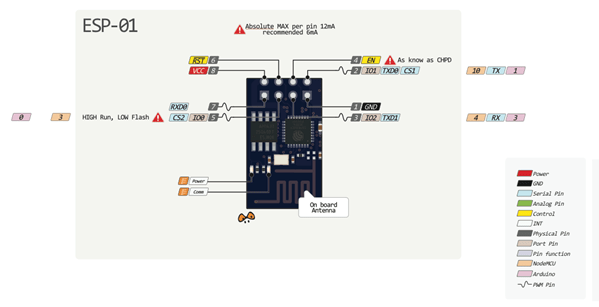

Contact description:
- 1 – ground, 8 – power. According to the documentation, the voltage is supplied up to 3.6 V - this is important to take into account when working with Arduino, which is usually supplied with 5 V.
- 6 – RST, needed to reboot the microcontroller when a low logic level is applied to it.
- 4 – CP_PD, also used to put the device into energy saving mode.
- 7 and 0 – RXD0 and TXD0, this is a hardware UART required for flashing the module.
- 2 – TXD0, an LED is connected to this pin, which lights up when the logic level on GPIO1 is low and when data is transmitted via UART.
- 5 – GPIO0, input and output port, also allows you to put the device into programming mode (when the port is connected to a low logic level and voltage is applied).
- 3 – GPIO2, input and output port.
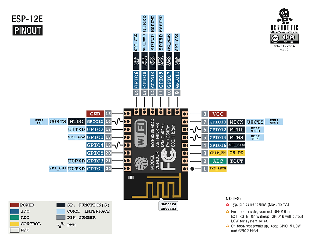
ESP-12 pinout
The main differences between Arduino and ESP8266
- The ESP8266 has a larger amount of flash memory, while the ESP8266 does not have non-volatile memory;
- ESP8266 processor is faster than Arduino;
- ESP8266 has Wi-Fi;
- ESP8266 consumes more current than Arduino;
Programming ESP8266 in Arduino IDE
The esp8266 development kit includes:
- Compiler from the GNU Compiler Collection.
- Libraries, WiFi, TCP/IP protocol stacks.
- A means of loading information into the controller program.
- Operating IDE.
Initially, ESP8266 modules are supplied with firmware from the manufacturer. With its help, you can control the module from an external microcontroller and work with Wi-Fi as a modem. There are also many other ready-made firmwares. Some of them allow you to configure the module’s operation using a WEB interface.
Can be programmed from Arduino environment IDE. With its help, you can easily write sketches and upload them to the ESP8266, flash the ESP8266, and do not require the Arduino board itself. Arduino IDE supports all kinds of ESP8266 modules.
IN currently The following functions can be implemented for ESP8266:
- Basic functions of the Wiring language. You can control the GPIO ports in the same way as the pins on the Arduino board: pinMode, digitalRead, digitalWrite, analogWrite. The analogRead(A0) command allows you to read ADC values. Using the analogWrite (pin, value) command, you can connect PWM to the right exit GPIO. When value=0 PWM is disabled, maximum value reaches a constant equal to 1023. Using the attachInterrupt and detachInterrupt functions, you can interrupt on any GPIO port except 16.
- Timing and delay. Using the millis and micros commands you can return the ms and μs that have passed since the start. Delay allows you to pause program execution for right time. Also, the delay(…) function allows you to support normal work Wi-Fi, if present in the sketch large elements, which take more than 50 ms to complete. Yield() is an analogue of the delay(0) function.
- Serial and Serial1 (UART0 and UART1). Serial work on ESP8266 is similar to work on Arduino. Writing and reading data blocks code execution if the 128-byte FIFO and 256-byte software buffer are full. The Serial object uses hardware UART0, you can set pins GPIO15 (TX) and GPIO13 (RX) for it instead of GPIO1(TX) and GPIO3(RX). To do this, after the Serial.begin(); you need to call Serial.swap();. Similarly, Serial1 uses UART1, which works for transmission. The required pin for this is GPIO2.
- Macro PROGMEM. Its operation is similar to that of Arduino. Allows you to move read data only and string constants in flash memory. At the same time, the ESP8266 does not store the same constants, which leads to additional waste of flash memory.
- I2C. Before working with the I2C bus, the buses are selected using the Wire.pins(int sda, int scl) function.
- SPI, OneWire – fully supported.
Using esp8266 to communicate with Arduino over WiFi
Before connecting to Arduino, it is important to remember that the supply voltage of the ESP8266 cannot be higher than 3.6, while on the Arduino the voltage is 5 V. You need to connect 2 microcontrollers using resistive dividers. Before connecting the module, you need to familiarize yourself with the pinout of the selected ESP8266. The connection diagram for ESP8266-01 is shown in the figure.
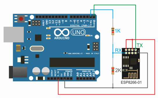
3.3 V from Arduino to Vcc&CH_PD on the ESP8266 module, Ground from Arduino to ground from ESP8266, 0 – TX, 1 – RX.
For support stable operation ESP8266 needs source DC voltage at 3.3 V and maximum current 250 mA. If food comes from USB-TTL converter, malfunctions and malfunctions may occur.
Working with the Wi-Fi library for the ESP8266 is similar to the library for a regular shield. There are several features:
- mode(m) – to select one of three modes: client, access point, or both modes at the same time.
- softAP(ssid) – needed to create an open access point.
- softAP(ssid, password) – creates an access point with a password, which must consist of at least 8 characters.
- WiFi.macAddress(mac) and WiFi.softAPmacAddress(mac) – defines the MAC address.
- WiFi.localIP() and WiFi.softAPIP() – determining the IP address.
- printDiag(Serial); – will allow you to find out diagnostic data.
- WiFiUDP – support for sending and receiving multicast packets in client mode.
The work is performed according to the following algorithm:
- Connecting USB-TTL to USB and to ESP.
- Launching Arduino IDE.
- Select tools from the menu desired port, board, frequency and size of flash memory.
- File - Examples - ESP8266WiFi - WiFiWebServer.
- Write down the SSID and password of the Wi-Fi network in the sketch.
- Start compiling and uploading code.
- Wait for the firmware process to finish, disconnect GPIO0 from ground.
- Set the speed to 115200.
- A connection will occur and the IP address will be recorded.
- Open browser, enter address bar IP number/gpio/1
- Look at the port monitor; if an LED is connected to the GPIO2 output, it should light up.
NodeMCU based on esp8266
 NodeMCU is a platform based on the esp8266 module. Used to control the circuit remotely using the Internet via Wi-Fi. The board is small-sized, compact, inexpensive, and has a USB connector on the front side. Nearby are buttons for debugging and rebooting the microcontroller. An ESP8266 chip is also installed. Supply voltage is from 5 to 12 V, it is advisable to supply more than 10 V.
The board's big advantage is its low power consumption. They are often used in schemes with self-powered. There are only 11 general purpose ports on the board, some of which have special functions:
- D1 and D2 – for I2C/ TWI interface;
- D5-D8 - for SPI interface;
- D9, D10 – for UART;
- D1-D10 – can work as PWM.
The platform has a modern API for hardware input and output. This allows you to reduce the number of steps when working with equipment and when setting it up. With the help of NodeMCU firmware, you can use the full working potential for rapid development devices.
WeMos based on esp8266
 WeMos is another type of platform based on the esp8266 microcontroller. Accordingly, there is Wi-Fi module, Arduino IDE supported, has a connector for external antenna. The board has 11 digital inputs/outputs, which (except D0) support interrupt/pwm/I2C/one-wire. The maximum supply voltage reaches 3.3 V. There is also a USB connector on the platform. Analog input 1 with a maximum voltage of 3.2V.
To work with the module, you need to install the CH340 driver and configure the Arduino IDE for the ESP8266. To do this, you need to add the address http://arduino.esp8266.com/stable/package_esp8266com_index.json in the settings menu in the “additional link for board manager” line.
After this, you need to find the esp8266 by ESP8266 package and install it. Then you need to select the Wemos D1 R2 microcontroller from the tools menu and write down the desired sketch.
Conclusions on ESP8266
With boards based on the ESP8266 chip, you can add capabilities to your projects. big internet”, making them much more intelligent. Remote control, collecting and analyzing data on the server, voice processing and working with images - all this becomes available when we connect our project via WiFi to the Internet. In the following articles, we will take a closer look at how you can program esp8266-based devices, and also pay attention to such popular boards as WeMos and NodeMcu.

Miniature WiFi modules ESP8266 are quite attractive for smart home and home automation systems. They are also called “NRF24L01 killers.”
I ordered myself later modifications ESP07 and ESP12, which are different smaller sizes And a large number derived GPIOs, which does not require “hacks” to use additional I/O ports in them.
These modules were developed by a Chinese company
Specifications:
- WI-FI: 802.11 b/g/n with WEP, WPA, WPA2.
- Operating modes: Client (STA), Access Point (AP), Client+Access Point (STA+AP).
- Supply voltage 1.7..3.6 V.
- Current consumption: up to 215mA depending on operating mode.
- Number of GPIOs: 16.
- Flash memory size 512kb.
- Data RAM 80 kB
- RAM instructions - 32 kb.
I ordered the modules in January.
Price - $3.78, - $4.24. I bought it as a reward for reviewing an article. Arrived in 31 days in sealed bags 


ESP8266 ESP-07


ESP8266 ESP-12


Reviving the module took quite a long time
To do this, you need to apply 3.3V to it. Moreover, the stabilizers for USB/UART converters do not work this module according to current, so external power is needed.
RXD, TXD and GND are connected via to the computer.
As a result, I assembled the following circuit on a breadboard: 
Here I immediately encountered the following difficulty - the pitch of the holes on the ESP07 is 2 mm, and not 2.5 like the pin connectors used in Arduino and other places.
I had to solder wires to the breadboard 


Immediately brought it out RESET button and a GPIO0 jumper to ground, which switches the module to firmware download mode. And I connected power to the module through
After that, I launched the CollTerm program and received a module invitation at a speed of 9600.
The AT+GMR command returned 0020000904 ( SDK version- 0020, AT version - 0904)

For those who are too lazy, like me, to deal with AT commands, there is a tool that allows you to configure all this.
I did the firmware. Because this program works only with COM1-COM6, I had to change my COM33 from USB/UART converter to COM6 in the device manager.
Further, installing the firmware is not difficult: open the port and connect. The speed is selected automatically. The main thing is not to forget to connect GPIO0 to ground (I have a special jumper for this). The speed is selected automatically. Sometimes the connection was not established. Pressing the RESET button during the connection helped.


Now you can connect to the module
In this program you can download ESP files for the LUA interpreter, execute both single commands and scripts of this interpreter.

I was able to run the BMP180 pressure/temperature module connected to GPIO2 and GPIO0 
To do this, I downloaded the bmp180.lua file from the ready-made modules that came with the firmware from GITHUB
And then the init.lau file executed when the ESP8266 boots
tmr.alarm(1, 5000, 1, function() print("ip: ",wifi.sta.getip()) bmp180 = require("bmp180") bmp180.init(4, 3) tmr.stop(1) -- alarm stop end)
Running the program without delaying the timer resulted in an invariable error.
After restart, code
bmp180.read(OSS) t = bmp180.getTemperature() p = bmp180.getPressure() -- temperature in degrees Celsius and Farenheit print("Temperature: "..(t/10).." C") -- pressure in differents units print("Pressure: "..(p * 75 / 10000).." mmHg")
Output the current pressure and temperature to the console.
But I was unable to start issuing these parameters in web server mode. It's all about lack of memory. The web server and BMP180 worked separately, but together they crashed
PANIC: unprotected error in call to Lua API ( error loading module "bmp180" from file "bmp180.lua": not enough memory)
Or scraps of LUA code just fell onto the console.
It was not possible to modernize on the fly.
My further path was to build my firmware on a proprietary SDK, like . But that is another story. I’ll just say that the firmware was assembled without problems, but it was not possible to launch the ill-fated BMP180.
conclusions
- ESP8266 modules are a very cheap solution for building a smart home network and other home automation using WiFi
- These modules are quite suitable for replacing the NRF24L01+ in conjunction with Arduino and other “popular” controllers.
- To work as an independent controller, the ESP8266 has few resources and rather crude firmware
- Programming ESP modules is a rather labor-intensive process that can be intimidating for beginners
- Overall, the ESP8266 has great promise. I will wait for the development of firmware and development tools, but for now, I will use them in conjunction with other controllers (except )))