Electronics courses. For a beginning radio amateur, simple circuits, simple circuits, literature for a beginning radio amateur
In everyone’s life, situations arise when it is necessary to repair some radio-electronic device, from a Christmas tree garland to a complex household appliances. With minimal skills in working with tools, many types of work can be done independently. This is usually limited to soldering a broken wire or searching for a burnt-out lamp. More serious types of work require knowledge in the field of electronics, experience, equipment and tools.
Knowledge will not be superfluous at all, but you should not immediately try to comprehend the structure and repair, in particular, of a TV. Most likely, nothing will come of this. At best, the repair will fail, and at worst, new problems will be added. It is better to start studying radio and electrical engineering from the very basics and consolidate them practical work. To do this, you need to start with a very small fleet of tools and devices, which can then be replenished as the need arises.
What you need to know
It is best to take radio electronics lessons from more experienced people, but in the era of the widespread development of the Internet, it is quite possible to master knowledge on your own. There is a sufficient number of training videos and accessible literature on the Internet for free reference. If you wish, you can even subscribe to training courses and lessons.
What a novice radio amateur should know, and what must be present in the training course:
- Basics of Electronics. These are, first of all, Ohm's laws, Kirchhoff's laws, and power calculations. It is necessary to know the calculation of sequential and parallel connection resistors and capacitances. Without this knowledge, further steps are simply pointless;
- Know how to use measuring instruments. For everyone measuring instruments it is important to be able to choose the correct measurement limit, and for dial gauges - additionally to be able to determine the value of the measurement scale division and take readings;

- Know the operating principle and structure of the simplest radioelements: resistors, capacitors, inductors, transformers, diodes and transistors. It is necessary to navigate the parameters of the elements and, based on the operation of the circuit, determine which of them are the most important and critical in a given section of the circuit. At first, there is no need to thoroughly know how it works p-n junction diode and transistor, but the operating features that characterize the most important parameters, you need to remember;
- Be able to read radios and electrical diagrams. To do this, you need to remember the designations of elements on circuit diagrams;
- Know the principles of labeling radioelements, be able to decipher abbreviated and coded designations and be able to convert multiple measurement values (megaohms into kiloohms, microfarads into picofarads, and so on);

- Know how to use a soldering iron, choose the right solder and flux for soldering.
Important! Most radio circuits, although they require power, low voltage, but uses for these purposes the conversion of mains voltage, which is dangerous to life. Basic safety precautions are important for maintaining health and life.
What tools and equipment are needed
A radio amateur workshop must have several mandatory items. Over time, with the acquisition of skills and knowledge, the range can be expanded, but at first only a few varieties are needed.
Most main tool radio amateur - soldering iron. To ensure safety and prevent electric shock or damage to circuit elements, the soldering iron must be low-voltage - with a supply voltage of no more than 42V. If we talk about power, then a 25-watt soldering iron is enough for soldering most circuit elements. It is, of course, not very suitable for soldering leads of powerful radio components, and if in doubt, you can take a tool with a power of 40W. No longer necessary, because even in in capable hands using such a soldering iron can lead to overheating and failure of radioelements, and peeling of printed conductors on boards.

It makes no sense for a novice radio amateur to purchase a complex and expensive soldering station. Having learned how to use a regular soldering iron correctly, you can think about purchasing a more complex tool, but having learned to work with a soldering station, it will be quite difficult to handle a regular soldering iron.
Meter
Currently on sale you can find a wide variety of all kinds of measuring instruments, varying degrees of complexity, accuracy and price range.
When working with electrical diagrams The most important measurement is the following parameters:
- Resistance;
- AC and DC voltage;
- Variable and D.C.;
- More complex work will require measuring the frequency and shape of signals, transistor parameters, and inductance values.
The most common combination instruments measure voltage, current and resistance. Previously, they were called avometers (ampere-volt-ohmmeter), but now, mainly, testers or multimeters, since they are capable of measuring several more parameters.
Most devices are based on digital processing signals and have a symbolic indication. Like most digital devices, they have many positive qualities:
- High measurement accuracy;
- Opportunity automatic detection measurement limit and signal polarity;
- Remembering the result.

At the same time, analog instruments, having less accuracy, allow you to see a clear change in the measured value according to the position of the arrow. It is possible to observe and measure rapidly changing parameters.
Digital devices require some time to set the readings. The main disadvantage is the requirement to initially know the correct polarity of the signal source and its possible value in order to select the measurement limit. This is also the reason for the difficulty that beginner radio amateurs have - correctly reading the readings of the pointer instrument.
With an analog device, if you have some skill, you can monitor the condition and serviceability of electrolytic capacitors, which is very difficult to do with a digital multimeter.
It is better for a beginner to use exactly pointer device, since during the training process useful skills in working with measuring equipment are acquired, and measurement accuracy is not fundamental. In addition, such a device does not require a built-in power supply to measure current and voltage.
For a novice radio amateur, even a tester released in the middle of the last century is quite suitable, since the measurement principle, rules of use and characteristics of avometers have practically not changed since that time, and the accuracy and reliability of even the oldest devices is sometimes much higher than that of modern cheap Chinese avometers. The amateur radio hobby of most modern electronics engineers began with the most common tester domestic production Ts20.

Tools and materials
A radio amateur laboratory is impossible without a minimum of tools:
- Nippers (side cutters);
- Tweezers;
- A set of screwdrivers with various blade shapes;
- A set of various fasteners (bolts, nuts, washers);
- Insulated flexible and single-core wires.
Solder and flux are required. The greatest confidence uses POS60 type solder, which has a low melting point. Both before and now it is the main solder for soldering radioelements in the post-Soviet space.
Rosin or its solution in ethyl alcohol is mainly used as a flux. You can use other compositions, for example, LTI120, but rosin is more versatile and has a minimal cost.

Important! When soldering radioelements and wires, do not use acidic or active fluxes. Quickly and efficiently performed soldering will be hopelessly damaged by corrosion after a short time.
Safety precautions
Radio technology for beginners should provide the most high level security. It has already been noted about low-voltage soldering irons, but it should be noted that most hobbyists immediately use network blocks nutrition. It will be much safer to purchase or ask to make a powerful isolation transformer with a unity transformation ratio for your home laboratory. Giving the same output voltage AC 220V, it will provide reliable galvanic isolation from the mains.
Video
Beginning radio amateurs who are not very well versed in electronics will find it difficult to implement the circuits and various devices. They will not undertake their manufacture because of the multitude simple questions and obstacles that arise on their way.
Therefore, below is the basic information that will help you take the first step into the mysterious world of radio electronics.
Electronic device board

The simplest circuit board of an electronic device is a plate of insulating material (fiberglass, getinax...), on one side of which there are active and passive components, and on the other side there are strips of copper foil with contact pads (tracks) that play the role of connecting conductors.
The component leads are passed through holes in the board and soldered with tin-lead solder to contact pads. Now let's move on to a detailed consideration of the various components, a list of which for each specific device is given after its description.
PCB
Topology printed circuit board, as a rule, is given on a scale of 1:1. It shows a diagram of all the connections between the various components or external elements devices. In the pictures it is shown from the metallization side of the print. It is recommended to use foil fiberglass as the board material. It is highly durable and easy to work with. Getinax is also suitable, although it often crumbles, especially when drilling with an insufficiently sharp drill.

There are several methods for creating a pattern (or "printing" as it is often called) on the metalized side of the board.
The highest quality prints can be made using photolithography. To do this, a layer of a special photosensitive material called photoresist is first applied to the board on the copper foil side. Then, ultraviolet (UV) radiation is irradiated through a mask with an image of the print pattern. After processing in special reagents, only those areas of the photoresist that were not exposed to UV radiation remain on the surface of the board. After fixing the photoresist - special heat treatment - it acquires the required mechanical and chemical stability. If you then treat the board in a ferric chloride solution, the part of the copper foil not covered with photoresist will be etched off. The final operation is to remove the attached photoresist using an organic solvent.
Even brief description This process gives you an idea of how complex it is, not to mention the fact that it requires special equipment (UV emitter, centrifuge for applying photoresist, oven with temperature control) and various chemicals. Of course, this method is absolutely unacceptable at home.
Fortunately, radio amateurs have come up with many completely available ways manufacturing of printed circuit boards. So, in order to protect the foil tracks, you can use a chemically resistant varnish applied using a glass pen or pen refill from which the ball, strips of adhesive tape or insulating tape have been removed. On the same board, you can combine these methods, depending on the required accuracy of reproduction of its individual sections.
However, before you begin creating the connection path pattern, we strongly recommend that you drill all of the design-provided holes for component leads and pin connections. If you push this operation to the next stage, the likelihood of damaging the metallization tracks will increase.
DRILLING HOLES
First, you should mark the holes exactly according to the drawing. Experienced radio amateurs use graph paper for this, on which they mark the centers of future holes. By gluing the sheet onto the board using silicate or casein glue, you get a simple but fairly accurate template. Drills for fiberglass must be well sharpened, otherwise the drill may move away from the center of the marking when drilling.
It is most convenient to perform this operation on a drilling machine. However, you should not be upset if you do not have such an opportunity. Using a hand or electric drill, powered or powered battery, you can achieve the required drilling accuracy. It is advisable to first drill all the holes with a thin drill with a diameter of 0.8-1.3 mm, and then drill out those whose diameter should be larger (for example, mounting holes).
ETCHING THE BOARD
Methods for protecting connecting tracks on a board can be completely different. To bleed off excess areas of copper foil, copper sulfate, ferric chloride and other reagents are usually used. It is convenient to etch the board in a plastic bath (for example, for developing photographs). You can also use an old porcelain saucer or glass jar.
Ferric chloride solution
A ferric chloride solution of working concentration has a fairly high viscosity, so it is recommended to shake the container to ensure constant update active substance at the surface of the board. It is necessary to control the etching process. If in the second case you can ruin a sheet of photo paper, then in the first you risk canceling the results of your own work invested in making the protective pattern on the board. The fact is that as a result of etching the side surfaces of the tracks, their thickness gradually decreases and, if you leave the board in the solution for long time, the thinnest of them may disappear completely.
Attention! Ferric chloride stains on clothing are almost impossible to remove.
The etching operation ends by thoroughly washing the board in tap water. The film that protected the tracks during etching can be easily removed using a solvent or sandpaper. Copper traces will oxidize less during operation, and soldering of component leads will occur faster and better if they are first degreased with acetone or pure gasoline and then tinned with solder.
PASSIVE COMPONENTS
This category includes ordinary resistors of all denominations and sizes, as well as variable and tuning resistors, the resistance at the terminals of which can be adjusted. This also includes capacitors, transformers and inductors.
Resistors (resistance)
On schematic diagrams, that is, diagrams depicting the structure of the connection of components, resistors are usually denoted by the Latin letter “R”. To the right of it is written serial number resistor, allowing you to find it on the circuit and wiring diagrams, as well as in the table where its parameters are indicated - nominal resistance value, power, etc.

The unit of resistance is in international system SI is om and its symbol- Q (omega). Units derived from the ohm are obtained by adding letters indicating the multipliers adopted in this system.
So, 1 MOhm = 1 LLC kOhm = 1 LLC LLC Ohm. Resistor markings can be color-coded, as well as symbolic, that is, such that the rating, power and tolerance group are indicated using an alphanumeric code.
For example, resistor R with four colored stripes has a nominal value of 390 kOhm. The first orange ring on its body corresponds to the number 3, the second white ring corresponds to the number 9, and the third yellow ring indicates the multiplier - 10,000. Therefore, the resistance value of R5 is 39 X 10,000 = 390,000 Ohms = 390 kOhms. The fourth ring determines the tolerance group (for example, bronze marking corresponds to a deviation from the nominal value within ±5%).
The polarity of the resistors on the board does not matter. There is a standard range of resistor values. For example, in the ±10% tolerance group between 10 and 100 Ohm ratings, you can only find the following values: 12, 15, 18, 22, 27, 33, 39, 47, 56, 68 and 82 Ohms.
Capacitors
Capacitors are often called capacitors, which quite aptly characterizes them as “reservoirs” for storing electrical charges. The SI unit of capacitance is the farad (F). In practice, such capacitance values are very rare.
For example, the calculated electrical capacitance Globe does not reach one farad. Therefore, in electronics, units derived from the farad are used: microfarads (μF), nanofarads (nF) and picofarads (pF): 1 F = 1000 mF = 1,000,000 μF = 10^9 nF = 10^12 pF.
Depending on the purpose used various types capacitors, whose names come from the type of dielectric material that separates positive and negative charges. Capacitors are ceramic, paper, film, etc.

Ceramic capacitors have capacitance ratings ranging from a few picofarads to a few nanofarads. The capacitance of film capacitors is usually in the range of 1-1000 nF. The capacitor value is mainly given in alphanumeric designation, for example 102 is 1000 pF, 103 is 10,000 pF or 10 nf, etc.
If for the above capacitors the switching polarity does not matter, then for the so-called “electrolytic” capacitors the correct direction of voltage is an indispensable condition for their operation, and in some cases, for the safety of others. Incorrect inclusion electrolytic capacitor is fraught with its rapid heating, leading to boiling of the electrolyte contained in it. The capacitor housing cannot withstand the internal pressure and ruptures!
The polarity of electrolytic capacitors is usually indicated on the housing. While quite acceptable in size, electrolytic capacitors usually have a rating from 0.47 to 10,000 µF and higher, which is determined by the specific design.
Any technical solution is a compromise in which high performance in one of the parameters is achieved by reducing others. In the case of electrical capacitors, in order to achieve high capacitance values, accuracy and durability had to be sacrificed. The lifespan of such capacitors is several times less than that of their ceramic and film counterparts.
Finally, you should pay attention to the fact that the operating voltage indicated on the body of any type of capacitor must be no less than that shown in the diagram.
Transformers
Electronic devices operating on other AC mains voltages require the use of voltage transformers. The transformer is a core of a closed structure, made of special steel, on which one (or more) coil with an insulated copper (less often aluminum) wire is mounted, laid in the form of several windings with different numbers of turns.
The design of transformers can be completely different:
![]()
The power of a transformer, expressed in volt-amperes (VA), determines its load capacity, that is, the rated power that it can deliver to the load without overheating. The location of the leads of the primary and secondary windings eliminates the possibility of incorrect installation on the board.
ACTIVE INGREDIENTS
IN in this case We are talking about semiconductor devices, without which the existence of modern electronics would be unthinkable.
For all components of this class, the polarity of connecting the pins to the circuit is of fundamental importance.
The second important condition is that when soldering leads of active components, overheating is absolutely unacceptable!
Semiconductor diodes
On the schematic diagram of the device semiconductor diodes usually denoted by the letters “VD”. The image of a diode in the diagram resembles an arrow directed from its anode to its cathode. This direction, as a rule, coincides with the direction of current through the diode in the open state.

An exception is the semiconductor diode voltage stabilizer - zener diode. It is usually connected in reverse polarity with respect to the supply voltage. Its function is to limit the voltage to a certain level, called threshold voltage Zener diode.

A special type of semiconductor device is LED. He is capable of transforming electrical energy into electromagnetic radiation in the Visible or infrared (IR) range. The color of the glow depends on the semiconductor material used.

There are a wide variety of LEDs in shape and size: 3, 5 and 10 mm in diameter, round, flat, triangular, two-color, flashing, red, green, yellow, orange and even blue :) Before installing the LED, you must check the markings of the cathode and anode. A resistor must be connected in series with the LED to limit the current of the device. For different types LEDs operating current value can be in the range from 10 to 50 mA.
Bipolar transistors
Bipolar transistor- “old-timer” in the family of semiconductor devices. Nevertheless, it continues to serve people regularly, along with integrated circuits, which have pretty much supplanted it for recent years in modern electronic devices. The transistor has three terminals: base, emitter and collector. Bipolar transistors There are two types of conductivity: p-p-p (reverse) or p-n-p (direct).
Soldering of the transistor leads is carried out strictly one by one, by briefly touching the contact point with a soldering iron. In this case, you need to pause between touches to allow the conclusions to cool. To avoid excessive overheating of the case, it is not recommended to shorten the leads of the transistor.

Transistors are also distinguished by rated power. There are transistors in a metal case connected to the collector. The metal casing serves to remove heat generated on the collector during the passage of high currents.
There are so-called “composite” transistors. This connection scheme is used when it is necessary to obtain a large current gain.
Integrated circuits
Integrated circuit is a miniature electronic device containing many semiconductor devices and other components housed in a single package with terminals for external connections. Depending on functional purpose There can be any number of pins.

The appendices provide pinout diagrams integrated circuits, used in the proposed devices. General recommendation on the installation of integrated circuits is that it is advisable to mount the microcircuits on special panels, previously soldered to the board. In this case, you eliminate the possibility of overheating a rather expensive and “capricious” component, such as a semiconductor microcircuit.
Installation of integrated circuits is carried out after all soldering operations are completed. Make sure that the position of the key on the panel matches the key on the printed circuit board!
SOLDERING WITH TIN-LEAD SOLDER (POS)
Soldering components with tin provides mechanical attachment and electrical contact. To do this, you will need an electric soldering iron with a power of 25-40 W, preferably equipped with a thermostat. The soldering iron should have a long, thin tip, which should be periodically cleaned with a damp sponge.
Tin-lead solder (40% tin and 60% lead) is often sold as a thin wire with a channel filled with oxygen-free flux. The melting point of solder is 180-190 °C. This produces vapors containing some lead. Therefore, while soldering, try not to inhale flux vapors. Work in a well-ventilated area with a constant supply of fresh air.
Let's first look at the usual AA battery. On its label you can read that it has a voltage of 1.5 volts... is this really true? Let's check it out!
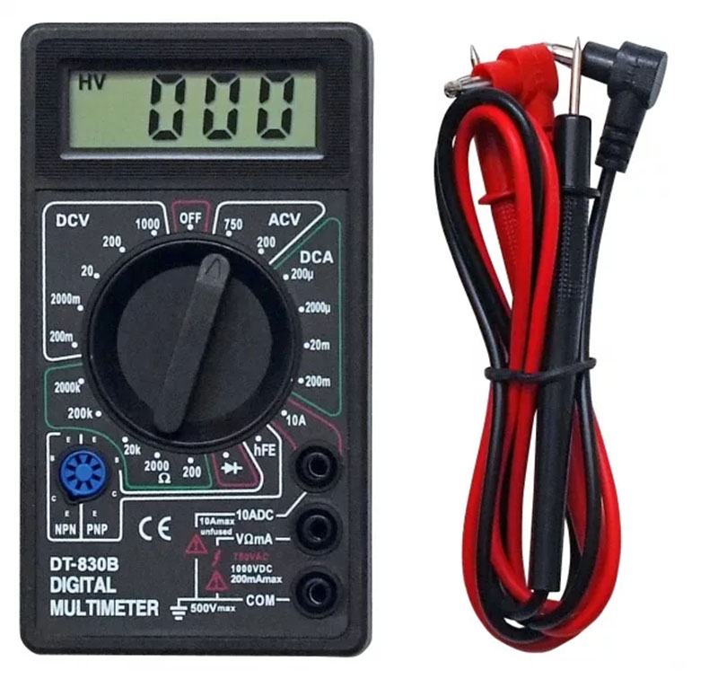
In order to find out we need digital multimeter. To begin with, it is worth purchasing an inexpensive model, always with manual selection of the measurement range.
- The black wire of the multimeter must be connected to the “COM” connector;
- The red wire must be connected to the connector for measuring voltage “V” ( Attention! Connecting wires in any other way may damage the device!)
- we expect to get a value of about 1.5 volts, so we set the multimeter knob to “20” in the DCV or V- area (the letter V with a dash means direct current) and, if necessary, turn on the device (some models turn on when you turn the knob) , and the multimeter should show 0;
- We touch the battery terminals with the metal tips of the multimeter probes... but which one goes where? Try both combinations - the result should be the same, only in one case will it be reflected positive number, and in another case the same number, but only with a minus sign.
- we read the value - in our case, the voltage of the new battery is 1.62 volts;
- turn off the multimeter.

ATTENTION! When taking measurements, to avoid damaging the multimeter, always select a measurement range larger than the maximum expected result! If we don't know what to expect, it would be safer to select a higher range and then reduce it later to get the most accurate result.
Since we have learned how to measure voltage with a multimeter, let's measure other batteries/accumulators! We chose for testing:
- charged battery 1.2 volts, size AA - the multimeter showed 1.34 volts.
- partially discharged Ni-MH battery(used in the camera) - our multimeter showed 1.25 volts.
Next, we will need 4 AAA batteries, a cassette for 4 batteries and a breadboard (you can find out what a breadboard is and how to use it). Let's install our 4 batteries in the cassette. Then insert the ends of the cassette wires into the holes of the breadboard as shown in the following photos:

The next step is to prepare the connecting wires (jumpers), they are also called jumpers. These are the wires that will connect individual radio components to each other. breadboard.
Of course, a certain number of jumpers are included in the kit along with the breadboard. But if you don’t have them, then it doesn’t matter, you can make them yourself.
For this we need: a computer cable, the so-called twisted pair, scissors or sharp knife.

First you need to remove the insulation from the cable. Inside the cable we see thin wires twisted together. The next step is to cut the wires to the required length. And the last thing that needs to be done is to strip about 1 cm of insulation from both ends.


Now we will assemble our first circuit on a breadboard. Let's take a 22kOhm resistor with colored stripes (red-red-orange-gold). What is the real resistance of this resistor? Let's check it with a multimeter!
- connect the red wire to the » Ω « connector
- we expect to get a value of about 22kOhm, so set the control to 200k in the Ω section and, if necessary, turn on the meter (some models turn on by turning the dial), which should show 0 before measuring;
- Touch the legs of the resistor with the metal tips of the multimeter probes;
- look at the value - our resistance is 22.1 kOhm;
- turn off the multimeter.

As with a battery, the value measured by a multimeter differs from the nominal value of the element being tested (resistor). Let us remind you that the gold stripe on the resistor (see the meaning of the colored stripes in this) means a tolerance of 5%, that is, 22 kOhm x 5% = 1.1 kOhm
Therefore, the resistance deviation range for our resistor can be from 20.9 kOhm to 23.1 kOhm.
Now let’s connect a cassette with batteries and a resistor on the breadboard as shown in the picture below:

In electronics, to depict connections between separate elements use circuit diagrams. In our case, the diagram will look like this:

The symbol marked B1 is our batteries, providing a total voltage of 4 x 1.5V = 6V. our 22 kOhm resistor is designated R1.
According to:
I=U/R
I = 6V / 22kOhm
I = 6V / 22000 Ohm
I = 0.000273 A
I = 273 µA
Theoretically, the current in the circuit should be 273 µA. Let us remember that the resistance of the resistor can differ within 5% (for us it is 22.1 kOhm). The voltage supplied by the batteries may also differ from the nominal 6 volts and will depend on the level of discharge of those batteries.
Let's see what real voltage comes from 4 1.5 V batteries.
- connect the black wire to the “COM” connector;
- connect the red wire to connector “V”
- we expect to get a value of about 6V, so set the regulator to the value "20" in the DCV or V- section, if necessary, turn on the device, which should initially show 0;
- Use the metal tips of the multimeter probes to touch the wires coming out of the battery cassette;
- look at the result - our voltage is 6.5 V;
- turn off the multimeter.

Let's substitute the obtained values into the formula following from Ohm's law:
I=U/R
I = 6.5 V / 22.1 kOhm
I = 6.5 V / 22100 Ohm
I = 0.000294 A
I = 294 µA
To confirm the reliability of our calculations, we have no choice but to measure the actual current with a multimeter.
- connect the black wire to the “COM” connector;
- connect the red wire to the “mA” connector;
- we expect to get a value of 294 µA, so we set the regulator to a value of 2000µ in section A-, if necessary, turn on the device, which should initially show 0;
- To measure current, you need to connect a multimeter to the open circuit. With the metal tips of the multimeter probes we touch the legs of the jumper connecting the positive pole of the battery and the legs of the resistor;
- we read the value - our current is 294 µA;
- turn off the multimeter.

And in the end this lesson Here is a diagram showing the differences in connecting a multimeter when measuring voltage and current:

Determine the malfunction of parts, both installed on the board and in their “pure” form. Select analogues for replacement, learn by what basic criteria this is done, and determine the interchangeability of parts.
In practice, you will learn typical connection diagrams with examples of connection in the diagram real device. As an example, we will look at the circuits of the most common devices: power supply, laptops, monitors, chargers etc. As a result, you will be able to repair them yourself at the component level.
Exploring various electronic components, found in almost all household and industrial electronic devices without exception. Construction of circuits based on them, from elementary simple to more complex, with the construction of timing diagrams and a detailed study of ongoing processes
Studying the work operational amplifiers, comparators, logic elements. Small circuits are also assembled based on almost all of the listed elements, with the study of their operation, measurement of basic parameters or examination of circuits using an oscilloscope.
Study of the basic principles of operation of measuring instruments designed to measure resistance voltage current, visual examination electrical signals(oscilloscope)
Topologies for constructing circuits and examples of real circuits based on one or another topology will be considered. The features of these schemes and areas of application are described. Let's look at a few basic standard schemes construction of pulse power supplies, describes the features and areas of application of a particular circuit. Next, listeners will be asked real circuits(sheets with different power supply circuits were distributed) and they will have to independently determine the topology of this circuit. It is the determination of the topology of the circuit that 80% determines the success of further repairs, which in 99% of cases will have to be carried out without having a diagram of the specific power supply being repaired.
All listeners will be asked to examine several dozen electronic components of various designs; by power, by the method of marking (alphanumeric or color) and it tells what and how it is designated, what it is (diode, resistor, transistor, etc.) and what it is used for. What other design options exist and where are they installed, depending on the characteristics. We train repair technicians to help you identify the fault in any electronic circuit.
Practical training in troubleshooting electronic devices. You can bring something that doesn’t work from home, and here we, collectively or in groups, repair it. On practical exercises people bring payments from washing machines, hoverboards, power supplies and other equipment.
During the learning process, we give students various questions or tasks that have non-standard solutions so that they can not just memorize how this or that element works, but also be able to think for themselves and apply the acquired knowledge in practice.
As a rule, we meet the wishes of students and, according to their choice, place the main emphasis when studying circuits in the direction of computers, household appliances or telephones.
The course is suitable anyone who plans to understand the repair of any electronics. Household appliances, industrial and any other that operates under electronic control.
The courses will be interesting both for people with zero experience and for those who are already involved in equipment repair. To begin with, you can come to our center and see with your own eyes how the courses are conducted. You will be able to chat with the teacher and learn more about the course. We accept people of any age.
On any Monday you can come and try the electronics course absolutely free.
After completing the entire course, you will have the skills to repair any electronics. All our students can ask for advice or help at any time, and we will be happy to help. Bonus! all our students enroll in general group on Watsapp, where you can consult and share experiences. You will also have a discount on our other courses and, of course, a certificate of completion of electronics repair courses.
We train experienced and certified craftsmen who are fully prepared for the job. The experience and knowledge gained during the training will give you confidence in your abilities to open your own workshop for repairing modern electronics.
Make your own simple ones electronic circuits You can use it at home even without deep knowledge of electronics. In fact, at the everyday level, radio is very simple. Knowledge of elementary laws of electrical engineering (Ohm, Kirchhoff), general principles the work of semiconductor devices, skills in reading circuit diagrams, and the ability to work with an electric soldering iron are quite enough to assemble a simple circuit.
Radio amateur workshop
No matter how complex the scheme may have to be implemented, it is necessary to have minimum set materials and tools in your home workshop:
- Side cutters;
- Tweezers;
- Solder;
- Flux;
- Circuit boards;
- Tester or multimeter;
- Materials and tools for making the device body.
You should not purchase expensive professional tools and devices to begin with. Expensive soldering station or a digital oscilloscope will be of little help to a novice radio amateur. At the beginning of your creative journey, the simplest instruments are sufficient, on which you need to hone your experience and skills.
Where to start
Do-it-yourself radio circuits for the home should not exceed the level of complexity that you have, otherwise it will only mean wasted time and materials. If you lack experience, it is better to limit yourself to the simplest schemes, and as you gain skills, improve them, replacing them with more complex ones.
Typically, most literature in the field of electronics for beginner radio amateurs leads classic example manufacturing of simple receivers. This especially applies to classical old literature, which does not contain so many fundamental errors compared to modern literature.
Pay attention! These schemes were designed for the enormous power of transmitting radio stations in the past. Today, transmitting centers use less power to transmit and try to move into a range of more short waves. Don't waste time trying to make a working radio using a simple circuit.
Radio circuits for beginners should contain a maximum of two or three active elements - transistors. This will make it easier to understand the operation of the circuit and increase the level of knowledge.
What can you do
What can be done so that it is not difficult and can be used in practice at home? There can be many options:
- Apartment call;
- Christmas tree garland switch;
- Lighting for modding system unit computer.

Important! You should not design devices that operate on household AC power until you have sufficient experience. This is dangerous both for life and for others.
Quite simple circuits have amplifiers for computer speakers, made on specialized integrated circuits. Devices assembled on their basis contain a minimum number of elements and require virtually no adjustment.
You can often find circuits that need basic modifications and improvements that simplify manufacturing and configuration. But this should be done by an experienced master so that the final version is more accessible to a beginner.
What to use for the design
Most literature recommends designing simple circuits on circuit boards. Nowadays this is quite simple. There are a wide variety of circuit boards available with different hole and trace configurations.
The installation principle is that the parts are installed on the board in free seats and then necessary conclusions are connected to each other by jumpers, as indicated in the circuit diagram.

With due care, such a board can serve as the basis for many circuits. The power of the soldering iron for soldering should not exceed 25 W, then the risk of overheating radio elements and printed conductors will be minimized.
The solder should be low-melting, like POS-60, and as a flux it is best to use pure pine rosin or its solution in ethyl alcohol.
Highly qualified radio amateurs can themselves develop a printed circuit board design and make it on foil material, on which they can then solder radio elements. The design developed in this way will have optimal dimensions.
Design of the finished structure
Looking at the creations of beginners and experienced craftsmen, one can come to the conclusion that assembling and adjusting the device is not always the most difficult part of the design process. Sometimes a properly functioning device remains a set of parts with soldered wires, not covered by any housing. Nowadays, you no longer have to worry about making a case, because on sale you can find all kinds of sets of cases of any configuration and size.