PCI interface in a computer: types and purpose. Photo
Almost all modern motherboards are currently equipped with a PCI-E x16 expansion slot. This is not surprising: a discrete graphics accelerator is installed in it, without which creating a productive personal computer is generally impossible. It is about its background of appearance, technical specifications And possible modes work will be discussed further.
Background to the appearance of the expansion slot
In the early 2000s, with the AGP expansion slot, which at that time was used for installation, a situation arose when maximum level performance has been achieved and its capabilities are no longer sufficient. As a result of this, the PCI-SIG consortium was created, which began developing the software and hardware components of the future slot for installing graphics accelerators. The fruit of his creativity was the first PCI specification Express 16x 1.0.
Some companies, to ensure compatibility between the two discrete graphics adapter installation ports that existed at that time, developed special devices that made it possible to install outdated graphic solutions into the new expansion slot. In the language of professionals, this development had its own name - PCI-E adapter x16/AGP. Its main purpose is to minimize the cost of upgrading a PC by using components from the previous configuration system unit. But this practice has not become widespread due to the fact that video cards entry level on the new interface had a cost almost equal to the price of the adapter.
In parallel with this, more simple modifications this expansion slot for external controllers, which replaced the usual ones at that time PCI ports. Despite their external similarity, these devices were significantly different. If AGP and PCI could boast of parallel information transfer, then here PCI Express was serial interface. Its higher performance was ensured by a significantly increased data transfer rate in duplex mode(information in this case could be transmitted in two directions at once).
Transfer rate and encryption method
In the designation of the PCI-E x16 interface, the number indicates the number of lanes used for data transfer. IN in this case there are 16 of them. Each of them, in turn, consists of 2 pairs of wires for transmitting information. As noted, more high speed is ensured by the fact that these pairs operate in duplex mode. That is, the transfer of information can go in two directions at once.

To protect against possible loss or distortion of transmitted data, this interface uses a special information protection system called 8V/10V. This designation is deciphered as follows: for the correct and correct transmission of 8 bits of data, they must be supplemented with 2 service bits to perform a correctness check. In this case, the system is forced to transmit 20 percent of service information, which does not carry a useful load for the computer user. But this is the price to pay for reliable and stable work graphics subsystem of a personal computer, and you certainly can’t do without it.
PCI-E versions
The PCI-E x16 connector is externally the same on all motherboards. Only the speed of information transfer in each case may differ significantly. As a result, the performance of the device is also different. And this one has modifications GUI such:
- 1st PCI modification - Express x16 v. 1.0 had a theoretical throughput of 8 Gb/s.
- 2nd generation PCI - Express x16 v. 2.0 already boasted twice the value bandwidth- 16 Gb/s.
- A similar trend has continued for the third version of this interface. In this case, this figure was set at 64 Gb/s.

It is impossible to distinguish visually by the location of the contacts. At the same time, they are compatible with each other. For example, if you install a graphics adapter card in a version 3.0 slot that meets the 2.0 specifications at the physical level, then the entire processing system will automatically switch to the lowest speed mode (that is, 2.0) and will continue to function with a throughput of 64 Gb/s .
First generation PCI Express
As noted earlier, PCI Express was first introduced in 2002. Its release marked the emergence personal computers with several graphics adapters, which, moreover, could boast even with one accelerator installed increased performance. The AGP 8X standard allowed for a throughput of 2.1 Gb/s, and the first revision of PCI Express - 8 Gb/s.

Of course, there is no need to talk about an eightfold increase. 20 percent of the increase was used to transfer service information, which made it possible to find errors.
Second modification of PCI-E
The first generation of this one was replaced in 2007 by PCI-E 2.0 x16. 2nd generation video cards, as noted earlier, were physically and software compatible with the first modification of this interface. Only in this case did the performance decrease significantly graphics system up to the PCI Express 1.0 16x interface version level.
Theoretically, the information transfer limit in this case was equal to 16 Gb/s. But 20 percent of the resulting increase was spent on official information. As a result, in the first case, the actual transfer was equal to: 8 Gb/s - (8 Gb/s x 20%: 100%) = 6.4 Gb/s. And for the second execution of the graphical interface, this value was already this: 16 Gb/s - (16 Gb/s x 20%: 100%) = 12.8 Gb/s. Dividing 12.8 Gb/s by 6.4 Gb/s, we get a real practical performance increase of 2 times between the 1st and 2nd versions of PCI Express.
Third generation
Latest and most current update this interface was released in 2010. The peak speed of PCI-E x16 in this case increased to 64 Gb/s, and maximum power no graphics adapter additional food in this case it can be equal to 75 W.

Configuration options with multiple graphics accelerators in one PC. Their pros and cons
One of the most important innovations of this interface is the ability to have multiple x16 graphics adapters at once. In this case, video cards are combined with each other and form, essentially, a single device. Their overall performance is summed up, and this allows you to significantly increase the performance of your PC in terms of processing the output image. For solutions from NVidia this mode is called SLI, and for GPUs from AMD - CrossFire.
The future of this standard
The PCI-E x16 slot will certainly not change in the foreseeable future. This will allow more powerful video cards to be used as part of outdated PCs and thereby carry out a gradual upgrade of the computer system. Now the specifications for the 4th version of this data transfer method are being worked out. For graphics adapters in this case, a maximum of 128 GB/s will be provided. This will allow you to display the image on the monitor screen in “4K” quality or more.

Results
Be that as it may, PCI-E x16 is currently the only graphics slot and interface. It will still be relevant for a long time. Its parameters allow you to create both entry-level computer systems and high-performance PCs with several accelerators. It is precisely due to this flexibility that no significant changes are expected in this niche.
 Serial bus PCI Express, developed by Intel and its partners, is intended to replace the parallel PCI bus and its extended and specialized variant AGP. Despite their similar names, PCI and PCI Express buses have little in common. The parallel data transfer protocol used in PCI imposes restrictions on the bandwidth and frequency of the bus; The serial data transfer used in PCI Express provides scalability (the specifications describe PCI Express 1x, 2x, 4x, 8x, 16x and 32x implementations). On this moment The current bus version is 3.0
PCI-E 3.0
In November 2010, the PCI-SIG organization, which standardizes PCI Express technology, announced the adoption of the PCIe Base 3.0 specification.
The key difference from the previous two versions of PCIe can be considered a changed encoding scheme - now instead of 8 bits useful information out of 10 bits transmitted (8b/10b), 128 bits of useful information out of 130 bits sent can be transmitted via the bus, i.e. The payload coefficient is almost close to 100%. In addition, the data transfer speed has increased to 8 GT/s. Let us remember that this value for PCIe 1.x was 2.5 GT/s, and for PCIe 2.x - 5 GT/s.
All of the above changes led to doubling the bus bandwidth compared to the PCI-E 2.x bus. This means that the total PCIe 3.0 bus bandwidth in a 16x configuration will reach 32 Gb/s. The first processors to be equipped PCIe controller 3.0, steel Intel processors, created based on the Ivy Bridge microarchitecture.
Despite the more than threefold increase in PCI-E 3.0 bandwidth compared to PCI-E 1.1, the performance of the same video cards when used different interfaces not much different. The table below shows the test results GeForce GTX 980 in various tests. The measurements were carried out at one graphic settings, in one configuration, the PCI-E bus version was changed in the BIOS settings.
PCI Express 3.0 is still backwards compatible with previous versions PCIe.
PCI-E 2.0
In 2007, a new PCI Express bus specification, 2.0, was adopted, the main difference of which is double the bandwidth of each transmission line in each direction, i.e. in the case of the most popular version of PCI-E 16x, used in video cards, the throughput is 8 Gb/sec in each direction. The first chipset to support PCI-E 2.0 was Intel X38.
PCI-E 2.0 is fully backward compatible with PCI-E 1.0, i.e. All existing devices With PCI-E interface 1.0 can work in PCI-E 2.0 slots and vice versa.
PCI-E 1.1
The first version of the PCI Express interface, which appeared in 2002. Provided a throughput of 500 MB/s per line.
Comparison of operating speeds of different generations of PCI-E
The PCI bus operates at 33 or 66 MHz and provides 133 or 266 MB/sec of bandwidth, but this bandwidth is shared among all PCI devices. The frequency at which the PCI Express bus operates is 1.1 - 2.5 GHz, which gives a throughput of 2500 MHz / 10 * 8 = 250 * 8 Mbps = 250 Mbps (due to redundant coding for transmitting 8 bits of data, 10 bits are actually transmitted information) for each PCI Express 1.1 x1 device in one direction. If there are several lines, to calculate the throughput, the value of 250 Mb/sec must be multiplied by the number of lines and by 2, because PCI Express is a bidirectional bus.
| Number of PCI Express 1.1 lanes | One-way throughput | Total throughput |
| 1 | 250 MB/sec | 500 MB/sec |
| 2 | 500 Mb/sec | 1 GB/sec |
| 4 | 1 GB/sec | 2 GB/sec |
| 8 | 2 GB/sec | 4 GB/sec |
| 16 | 4 GB/sec | 8 GB/sec |
| 32 | 8 GB/sec | 16 GB/sec |
Note! You should not attempt to install a PCI Express card into a PCI slot, and conversely, PCI cards will not install into PCI Express slots. Nevertheless, PCI card Express 1x, for example, can be installed and, most likely, will function normally in a PCI Express 8x or 16x slot, but not vice versa: a PCI Express 16x card will not fit into a PCI Express 1x slot.
So, let's move on to the most interesting part. What is inside most of our computers today? Naturally, the PCI bus. Another question is why this particular tire. Let's try to figure it out.
So, the development of the PCI bus began in the spring of 1991 as an internal project of Intel Corporation (Release 0.1). The company's specialists have set themselves the goal of developing an inexpensive solution that would make it possible to fully realize the capabilities of the new generation of 486/Pentium/P6 processors (that's already half the answer). It was especially emphasized that the development was carried out “from scratch”, and was not an attempt to install new “patches” on existing solutions. As a result, the PCI bus appeared in June 1992 (R1.0). Intel developers abandoned the use of the processor bus and introduced another “mezzanine” bus.
Thanks to this solution, the bus turned out to be, firstly, processor-independent (unlike VLbus), and secondly, it could work in parallel with the processor bus without turning to it for requests. For example, the processor works with the cache or system memory, and at this time information is written to the hard drive over the network. Just great! In reality, of course, it’s not an idyll, but the processor bus load is greatly reduced. In addition, the bus standard was declared open and transferred to the PCI Special Interest Group, which continued to improve the bus (R2.1 is currently available), and this, perhaps, is the second half of the answer to the question “why PCI?”
The main features of the bus are as follows.

When developing the bus, its architecture included advanced technical solutions, allowing to increase throughput.
The bus supports a data transfer method called "linear burst". This method assumes that a packet of information is read (or written) "in one piece", that is, the address is automatically incremented for the next byte. Naturally, this increases the transmission speed of the data itself by reducing the number of transmitted addresses.
The PCI bus is the turtle that holds the elephants supporting the "Earth" Microsoft/Intel Plug and Play (PnP) PC architecture. The PCI bus specification defines three types of resources: two common ones (memory range and I/O range, as they are called Microsoft company) and configuration space - “configuration space”.

The configuration space consists of three regions:
- device-independent header region;
- region determined by the device type (header-type region);
- user-defined region.
The header contains information about the manufacturer and type of device - the Class Code field ( network adapter, disk controller, multimedia, etc.) and other service information.
The next region contains the memory and I/O range registers, which allow a device to be dynamically allocated a region of system memory and address space. Depending on the system implementation, device configuration is done either by BIOS (when performing POST - power-on self test) or by software. The expansion ROM base register similarly allows you to display ROM device V system memory. The CIS (Card Information Structure) pointer field is used by cardbus cards (PCMCIA R3.0). The Subsystem vendor/Subsystem ID is clear, and the last 4 bytes of the region are used to determine the interrupt and request/ownership time.
When it comes to any interfaces in context computer systems, you need to be very careful not to “run into” incompatible interfaces for the same components within the system.
Fortunately, when it comes to the PCI-Express interface for connecting a video card, there will be practically no problems with incompatibility. In this article we will look at this in more detail, and also talk about what PCI-Express is.
Why is PCI-Express needed and what is it?
Let's start, as usual, with the very basics. PCI-Express interface(PCI-E) is a means of interaction, in this context, consisting of a bus controller and the corresponding slot (Fig. 2) on motherboard(to generalize).
This high-performance protocol is used, as noted above, to connect a video card to the system. Accordingly, the motherboard has a corresponding PCI-Express slot, where the video adapter is installed. Previously, video cards were connected via AGP interface, but when this interface, simply put: “was no longer enough,” PCI-E came to the rescue, oh detailed specifications which we will talk about now.
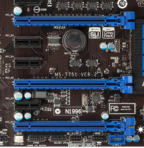
Fig.2 (PCI-Express 3.0 slots on the motherboard)
Key Characteristics of PCI-Express (1.0, 2.0 and 3.0)
Despite the fact that the names PCI and PCI-Express are very similar, their connection (interaction) principles are radically different. In the case of PCI-Express, a line is used - bidirectional serial connection, point-to-point type, there can be several of these lines. In the case of video cards and motherboards (we do not take into account Cross Fire and SLI) that support PCI-Express x16 (that is, the majority), you can easily guess that there are 16 such lines (Fig. 3), quite often on motherboards with PCI- E 1.0, it was possible to see a second x8 slot for operation in SLI or Cross Fire mode.
Well, in PCI, the device is connected to a common 32-bit parallel bus.

Rice. 3. Example of slots with varying amounts lines
(as mentioned earlier, x16 is most often used)
The interface bandwidth is 2.5 Gbit/s. We need this data to track changes in this parameter in different versions of PCI-E.
Further, version 1.0 evolved into PCI-E 2.0. As a result of this transformation, we received twice the throughput, that is, 5 Gbit/s, but I would like to note that in performance graphics adapters, didn’t really benefit, since it’s just a version of the interface. Most of the performance depends on the video card itself; the interface version can only slightly improve or slow down data transfer (in this case there is no “braking”, and there is a good margin).
In the same way, in 2010, with a reserve, the interface was developed PCI-E 3.0, at the moment it is used in all new systems, but if you still have 1.0 or 2.0, then do not worry - below we will talk about relatively backward compatibility different versions.
With PCI-E 3.0, the bandwidth has been doubled compared to version 2.0. There were also a lot of technical changes made there.
Expected to be born by 2015 PCI-E 4.0, which is absolutely not surprising for the dynamic IT industry.
Well, okay, let's finish with these versions and bandwidth figures, and we'll touch on very important question backward compatibility of different versions of PCI-Express.
Backwards compatible with PCI-Express 1.0, 2.0 and 3.0 versions
This question worries many, especially when choosing a video card for the current system. Since being content with a system with motherboard which supports PCI-Express 1.0, there are doubts whether the video card will work correctly with PCI-Express 2.0 or 3.0? Yes, it will be at least This is what the developers who ensured this compatibility promise. The only thing is that the video card will not be able to fully reveal itself in all its glory, but the performance losses, in most cases, will be insignificant.

On the contrary, you can safely install video cards with a PCI-E 1.0 interface in motherboards that support PCI-E 3.0 or 2.0; there are no restrictions at all, so rest assured about compatibility. If, of course, everything is in order with other factors, insufficient powerful block food, etc.
Overall, we've talked quite a bit about PCI-Express, which should help you clear up a lot of confusion and doubt about compatibility and understanding the differences between PCI-E versions.
What connectors are there on the motherboard and what are they for? You will learn about this in this article.
CPU socket or socket
The processor socket is a large rectangular socket. Typically, this connector is located at the top of the board.
There are connectors various types. In order to install the processor on the motherboard, it must be compatible with the socket on the board.
There are cases when the socket type of the processor and the board are the same, but the board does not support this processor model. As a result, such a connection motherboard and the processor will not work.
CPU socket or socket
Modern processors from Intel use the following types of connectors:
- Socket 1150
- Socket 1155
- Socket 1356
- Socket 1366
- Socket 2011
Modern processors from AMD use the following types of connectors:
- Socket AM3
- Socket AM3+
- Socket FM1
- Socket FM2
Connectors for installing RAM or slots
Connectors for installation random access memory- These are long vertical connectors located to the right or on both sides of the processor. Modern RAM slots on motherboards are of the DDR3 type.

Older motherboard models may use DDR2 or DDR1 connectors. All these types are not compatible with each other. Therefore, it will not be possible to install DDR3 into the DDR2 slot.
PCI Express slots
PCI Express slots are connectors on the motherboard that are designed to accommodate additional fees. These connectors are located at the bottom of the motherboard.

PCI EXPRESS slots
The PCI Express slot can be of several types: PCI Express x1, PCI Express x4 and PCI Express x16. In most cases, the PCI Express x16 slot is used to install video cards, and the remaining slots are used to install other expansion cards, such as sound cards.
There are three versions of PCI Express. These are PCI Express 1.0, PCI Express 2.0 and PCI Express 3.0. All these versions are fully compatible. This allows new PCI Express 3.0 capable devices to be installed into older PCI Express 1.0 motherboards. The only limitation is the data transfer speed. When installing a new device into an older version of PCI Express, the device will run at speeds old version PCI Express.
The PCI slot is an old connector for connecting expansion cards. Nowadays it is practically not used and is installed only in some motherboards.

The PCI connector can be found at the bottom of the motherboard, next to the PCI Express slots.
SATA connectors are connectors designed to connect hard drives, SSD drives and disk drives.

These connectors are located at the bottom of the motherboard and in most cases are colored red.
There are three versions of SATA, these are SATA 1.0, SATA 2.0 and SATA 3.0. All these versions are fully compatible and differ only in data transfer speed. For SATA 1.0 the speed is 1.5 Gbit/s, for SATA 2.0 – 3 Gbit/s, and for SATA 3.0 – 6 Gbit/s.
The motherboard power connector is located to the right of the RAM. It can consist of 20, 24 or 28 contacts.

You need to connect power from the power supply to this connector.
In contact with