Socket control via Bluetooth and Arduino. Turning Bluetooth devices on and off using Arduino (video)
Very often in your projects there is a need for remote control or data transfer from your telephone gadgets.
One of the most popular and widespread methods of data exchange via Bluetooth .
Today we will look at simple examples of how to connect Bluetooth module to Arduino and configure remote control from your phone.
We will need:
- Set of MALE-MAMA wires
- HC-06 Bluetooth
Connect Bluetooth The module to the Arduino microcontroller is most convenient using MALE-MAMALE wiring.
| Arduino | Bluetooth |
|---|---|
| Pin 1 (TX) | RXD |
| Pin 0 (RX) | TXD |
| GND | GND |
| 5V | VCC |
Be careful, you need to connect TX -> RXD ,RX -> TXD .
Now you need to write down the test code of the program:
When loading the sketch, it is necessary that the Bluetooth module is disconnected from the arduino microcontroller. Otherwise, the sketch will not be recorded because the connection with Bluetooth The module communicates via the same RX and TX ports as USB.
Int val; int LED = 13; void setup() ( Serial.begin(9600); pinMode(LED, OUTPUT); digitalWrite(LED, HIGH); ) void loop() ( if (Serial.available()) ( val = Serial.read(); / / When the character is "1", turn on the LED if (val == "1") ( digitalWrite(LED, HIGH); ) // When the character is "0", turn off the LED if (val == "0") ( digitalWrite(LED, LOW ); ) ) )
After the sketch is recorded and Bluetooth The module is connected to the Arduino, you can move on to the next step.
Connecting Bluetooth to your phone
It is advisable to use not USB as a power source for arduino, but an external 9 V power supply.
- Turn on Bluetooth on your phone and look for new devices
- We find in the list of disorders " HC-06" and connect to it.
- The phone will ask for a PIN code. you must enter " 1234 " or " 0000 "
- Hooray. The device is connected.
Now you need to download the bluetooth terminal to your phone. We will look at the example of the Android platform.


You can install different bluetooth terminals, as a rule they differ only in different designs, the functionality does not change. You can also find a terminal for iOS products.
After we have installed the terminal, we launch it, select our bluetooth module HC-06 and connect to it.
It's time to try the project in action. We write the number “0” in the terminal and send. LED L which is located on the arduino board next to pin 13 should go out. Now we send the number “1” through the terminal and the L LED should light up.
Demonstration of work:
Homework:
- Change the sketch so that the LED lights up and goes out using the same command, for example “G”.
- Add a sketch and teach it to convert text data coming via bluetooth into digital data and implement a dimer, light an LED using PWM, at a given brightness from 0 to 254 coming via bluetooth.
And work with him.
Motor Shield Upgrade
It turned out that the manufacturers of the Motor Shield module deprived their customers of the opportunity to install another module on top of their product. Apparently they like to be on top or just squeezed the normal contact panel.
This nuance does not suit me at all. That is why I decided to take up the soldering iron and bring the Motor Shield to a form convenient for me.

I carefully tore out the original contact sockets and threw them away.

I installed normal ones in their place.

In this form, the module has become much more convenient to use. Now I can properly connect the Bluetooth wires to the connectors, and not solder them tightly to the contacts on the Motor Shield.
Bluetooth module JY-MCU for Arduino

The JY-MCU Bluetooth module itself is quite tiny. The delivery set includes a cable for connection. The pin assignments are shown on the reverse side.

It can be powered from a 3.6-6V power source. This gives us the opportunity to connect it directly to the Arduino without using a regulator or voltage divider.
Code used when connecting to the device: 1234.
Connecting Bluetooth JY-MCU to Arduino Mega 2560
The connection is quite simple.
Official connection diagram:
- TXT on JY-MCU connect to RX (0) on Arduino
- Connect RXD on JY-MCU to TX (1) on Arduino
With this connection option, you will have to turn off the power to the Bluetooth module each time before loading the sketch. Don't forget about this.
I am not happy with this option, so I decided to use discrete ports with Serial support.
Unofficial connection diagram:
- VCC on JY-MCU is connected to +5V Arduino
- Connect GND on JY-MCU to GND Arduino
- TXT on JY-MCU connected to discrete PIN 50 on Arduino
- Connect RXD on JY-MCU to discrete PIN 51 on Arduino
Now you can upload sketches without turning off the power to the Bluetooth module.
To secure the Bluetooth, I decided to use a Proto Shield board and a miniature solderless breadboard. In the future I will connect other equipment, controls and displays to it.


Sketch for controlling a robot on Arduino via Bluetooth via an Android smartphone
In my sketch I implemented the following functions:
- Moving Forward
- Moving backwards
- Turn left
- Turn right
- Smooth left turn when moving forward
- Smooth right turn when moving forward
- Smooth left turn when moving backwards
- Smooth right turn when moving backwards
- Stop
Speed setting 0%
Speed setting 10%
Speed setting 20%
Speed setting 30%
Speed setting 40%
Speed setting 50%
Speed setting 60%
Speed setting 70%
Speed setting 80%
Speed setting 90%
Speed setting 100%
I used functions in the sketch so as not to duplicate code for similar events.
#include
// Connect the engine control library
#include// Connect the library for servos
#include// Connect the library to work with Serial via discrete ports //Create objects for engines
AF_DCMotor motor1(1); //channel M1 on Motor Shield - rear left
AF_DCMotor motor2(2); //channel M2 on Motor Shield - rear right
AF_DCMotor motor3(3); //channel M3 on Motor Shield - front left
AF_DCMotor motor4(4); //channel M4 on Motor Shield - front right// Create an object for the servo
Servo vsservo;SoftwareSerial BTSerial(50, 51); // RX, TX
// Create a variable for Bluetooth commands
char vcmd;
// Create variables to remember the speed of the motors
int vspdL, vspdR;
/* Create a variable whose value will decrease the speed during smooth turns.
The current speed must be greater than this value. Otherwise, the motors on the direction of rotation simply will not rotate */
int vspd = 200;void setup() (
// Set the Bluetooth data transfer rate
BTSerial.begin(9600);
// Set the data transfer speed over the cable
Serial.begin(9600);
// Select the pin to which the servo is connected
vservo.attach(9); // or 10, if plugged into the outermost connector
// Rotate the servo to 90 degrees each time it is turned on
vservo.write(90);
// Set the maximum rotation speed of the engines
vspeed(255,255);
}void loop() (
// If there is data
if (BTSerial.available())
{
// Read the commands and put them into a variable. char converts the command character code to a character
vcmd = (char)BTSerial.read();
// Send a command to the port so that they can be checked in the "Port Monitor"
Serial.println(vcmd);// Forward
if (vcmd == "F") (
vforward();
}
// Back
if (vcmd == "B")
{
vbackward();
}
// Left
if (vcmd == "L")
{
vleft();
}
// Right
if (vcmd == "R")
{
vright();
}
// Straight and left
if (vcmd == "G")
{
vforwardleft();
}
// Straight and right
if (vcmd == "I")
{
vforwardright();
}
// Back and left
if (vcmd == "H")
{
vbackwardleft();
}
// Back and right
if (vcmd == "J")
{
vbackwardright();
}
// Stop
if (vcmd == "S")
{
vrelease();
}
// Speed 0%
if (vcmd == "0")
{
vspeed(0,0);
}
// Speed 10%
if (vcmd == "1")
{
vspeed(25,25);
}
// Speed 20%
if (vcmd == "2")
{
vspeed(50,50);
}
// Speed 30%
if (vcmd == "3")
{
vspeed(75,75);
}
// Speed 40%
if (vcmd == "4")
{
vspeed(100,100);
}
// Speed 50%
if (vcmd == "5")
{
vspeed(125,125);
}
// Speed 60%
if (vcmd == "6")
{
vspeed(150,150);
}
// Speed 70%
if (vcmd == "7")
{
vspeed(175,175);
}
// Speed 80%
if (vcmd == "8")
{
vspeed(200,200);
}
// Speed 90%
if (vcmd == "9")
{
vspeed(225,225);
}
// Speed 100%
if (vcmd == "q")
{
vspeed(255,255);
}
}
}// Forward
void vforward() (
vspeed(vspdL,vspdR);
vforwardRL();
}// Forward for RL
void vforwardRL() (
motor1.run(FORWARD);
motor2.run(FORWARD);
motor3.run(FORWARD);
motor4.run(FORWARD);
}// Back
void vbackward() (
vspeed(vspdL,vspdR);
vbackwardRL();
}// Back to RL
void vbackwardRL() (
motor1.run(BACKWARD);
motor2.run(BACKWARD);
motor3.run(BACKWARD);
motor4.run(BACKWARD);
}// Left
void vleft() (
vspeed(vspdL,vspdR);
motor1.run(BACKWARD);
motor2.run(FORWARD);
motor3.run(BACKWARD);
motor4.run(FORWARD);
}// Right
void vright() (
vspeed(vspdL,vspdR);
motor1.run(FORWARD);
motor2.run(BACKWARD);
motor3.run(FORWARD);
motor4.run(BACKWARD);
}// Forward and left
void vforwardleft() (
if (vspdL > vspd) (
vspeed(vspdL-vspd,vspdR);
}
else
{
vspeed(0,vspdR);
}
vforwardRL();
}// Forward and right
void vforwardright() (
if (vspdR > vspd) (
vspeed(vspdL,vspdR-vspd);
}
else
{
vspeed(vspdL,0);
}
vforwardRL();
}// Back and left
void vbackwardleft() (
if (vspdL > vspd) (
vspeed(vspdL-vspd,vspdR);
}
else
{
vspeed(0,vspdR);
}
vbackwardRL();
}// Back and right
void vbackwardright() (
if (vspdR > vspd) (
vspeed(vspdL,vspdR-vspd);
}
else
{
vspeed(vspdL,0);
}
vbackwardRL();
}// Stop
void vrelease())(
motor1.run(RELEASE);
motor2.run(RELEASE);
motor3.run(RELEASE);
motor4.run(RELEASE);
}// Change speed
void vspeed(int spdL,int spdR)(
if (spdL == spdR) (
vspdL=spdL;
vspdR=spdR;
}
motor1.setSpeed(spdL);
motor2.setSpeed(spdR);
motor3.setSpeed(spdL);
motor4.setSpeed(spdR);
}
Bluetooth RC Car program - controlling a robot car from an Android smartphone
I installed the Bluetooth RC Car program on my smartphone. In my opinion, this is the best software for controlling a robot car.

The program allows you to transmit commands when pressing buttons or respond to data from the accelerometer in your smartphone, adjust the speed of movement with a slider, turn on the front and rear lights, turn on and off the sound signal, turn on and off the emergency signal.


The program requires Android version 2.3.3 or higher. The program size is 3 megabytes.
List of commands:
- F – forward
- B – back
- L – left
- R – right
- G – straight and left
- I – straight and to the right
- H – back and left
- J – back and right
- S – stop
- W – headlight on
- w – headlight is off
- U – tail light on
- u – tail light is off
- V – sound signal is on
- v – sound signal is turned off
- X – emergency signal is on
- x - the emergency signal is turned off
- 0 – movement speed 0%
- 1 – movement speed 10%
- 2 – movement speed 20%
- 3 – movement speed 30%
- 4 – movement speed 40%
- 5 – movement speed 50%
- 6 – movement speed 60%
- 7 – movement speed 70%
- 8 – movement speed 80%
- 9 – movement speed 90%
- q – movement speed 100%
As you can see, the testing ground for creativity is quite good. I would also add the ability to turn on the right and left lights separately for the front and rear headlights.
I have highlighted in bold the commands that are already supported in the sketch. I'm going to use the rest for another purpose.
The principle of transmitting commands: when you press a button in the program, the command is transmitted via Bluetooth once, and when the button is released, the S-stop command is immediately transmitted.
Demonstration of work
Next time I plan to connect an ultrasonic range finder to the robot and implement an obstacle avoidance algorithm.
This article shows different options for controlling relays in Arduino sketches. The examples were tested on Arduino Uno, but they can easily be applied to other Arduino boards: Uno, Mega, Nano.
Connection diagram
In this example, we use a standard one, on which all the necessary elements for connecting to it are already installed. The connection diagram is very simple: the relay module is connected to pin 5 of the Arduino board. In this case, for simplicity, we can not even connect a real load - the relay will click with each state change, we will hear these clicks and understand that the sketch is working.
Sketch for working with relays
/* * Sketch for controlling a relay using Arduino * We use the SONGLE SRD-05VDC relay * The relay OPENS when a low signal level (LOW) is applied to the control pin. * The relay CLOSES when a high signal level (HIGH) is applied to the control pin. * * In this example, we simply open and close the relay once every 5 seconds. * * PIN_RELAY contains the number of the pin to which the relay is connected, which we will control * * In the setup function, we set the initial position of the relay (closed) * If a load is connected to the relay (for example, a light bulb), then after running the sketch it will turn on and off every 5 seconds * * To change the blinking period, you need to change the parameter of the delay() function: setting 1000 milliseconds, you get 1 second of delay * * In real projects, the relay is turned on in response to the detection of any external events through the connection of sensors * */ #define PIN_RELAY 5 // Define the pin used to connect the relay // In this function we define the initial settings void setup() ( pinMode(PIN_RELAY, OUTPUT); // Declare the relay pin as an output digitalWrite(PIN_RELAY, HIGH); // Turn off the relay - send high signal) void loop() ( digitalWrite(PIN_RELAY, LOW); // Turn on the relay - send a low signal level delay(5000); digitalWrite(PIN_RELAY, HIGH); // Turn off the relay - send a high signal level delay(5000); )Sketch of relay control with motion sensor
In real projects, a change in the state of the relay should occur in response to some reaction of the environment. For example, in response to a signal from a triggered motion sensor, you can turn on the light by closing the circuit using a relay. In this sketch we will look at this connection option.
Relay connection diagram

It should be understood that in real projects they do without an Arduino at all - simply connecting the signal output of the sensor to a relay.
Sketch example
In this example, we will add a check of the state of the PIR sensor to the loop using the digitalRead() function. If we receive HIGH, then this means the sensor is triggered and we perform an action - turn on the relay. If you attach a light bulb to it, it will light up. But, as in the previous example, you can simply listen to the clicks.
/* Sketch for controlling an Arduino relay using a PIR sensor PIN_RELAY contains the number of the pin to which the relay that we will control is connected PIN_PIR contains the number of the pin with the connected PIR sensor In the setup function we set the initial position of the relay (closed) In the body of the loop function we check the presence high signal level from the sensor using the digitalRead function To debug the current value of the sensor, output it to the port monitor window */ #define PIN_RELAY 8 // Define the pin used to connect the relay #define PIN_PIR 5 // Define the pin used to connect the PIR sensor / / In this function we define the initial settings void setup() ( Serial.begin(9600); pinMode(PIN_RELAY, OUTPUT); // Declare the relay pin as an output digitalWrite(PIN_RELAY, HIGH); // Turn off the relay - send a high signal ) void loop() ( int val = digitalRead(PIN_PIR); // Read the value from the motion sensor into a separate variable if (val == HIGH) ( Serial.println("Sensor triggered"); digitalWrite(PIN_RELAY, LOW); // Turn on the relay - send a low signal level ) else ( digitalWrite(PIN_RELAY, HIGH); // Turn off the relay - send a high signal level ) delay(1000); // Check values once per second. )
Bluetooth in Arduino allows you to connect various devices wirelessly. You can transmit messages from Arduino sensors and controllers to Android devices and vice versa, receive commands from smartphones via bluetooth. In this article we will learn how to organize wireless operation of your Arduino project using the popular and not very inexpensive bluetooth modules HC05 and HC06. You won’t believe it, but connecting and programming Bluetooth modules is not at all a difficult task and is accessible even to beginners. Let's make sure of this.
Often projects require remote control or data transfer from a phone or other device. One of the most popular and convenient methods is data exchange via Bluetooth. The UART (Serial) interface is used to communicate between the Arduino board and the computer. Since any Arduino board has at least 1 UART serial port, no specialized libraries and circuits are required to connect a Bluetooth module.
The most popular modules are devices based on the BC417 chip. This series is called HC. Modules HC-03 and HC-05 can be both a connection server and a client; they have a wide range of AT commands.
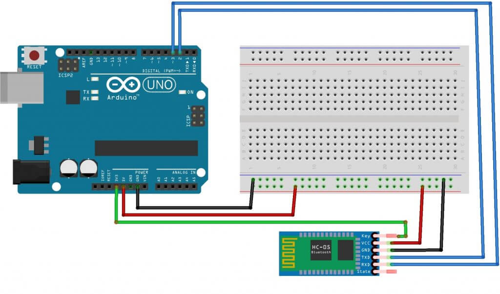
To connect to a PC you will need a Bluetooth module, Arduino board, connecting wires and a computer. The sketch for controlling the Arduino board via a smartphone and a computer will be the same, since in both cases the data will be sent to the microcontroller via the UART protocol. The diagram for connecting the Bluetooth module to the board is shown in the figure. The RX pin on the Arduino is connected to TDX, TX to RDX, GND to GND, 5V to VCC.
When uploading the sketch, you need to disable the Bluetooth module, otherwise an error accessing Arduino will appear. You also need to install an application on a smartphone or tablet that supports Android OS to send data to the module. After installing the application, you need to download the sketch and connect the module to the Arduino board. LED flash code example:
Int val; void setup() ( Serial.begin(9600); pinMode(13, OUTPUT); // 13 pin is an LED, declared as an output ) void loop() ( if (Serial.available()) // checking submitted commands ( val = Serial.read(); if (val == "1") (digitalWrite(13, HIGH);) // at 1 the LED turns on if (val == "0") (digitalWrite(13, LOW);) / / at 0 the LED turns off ) )
Now you need to configure the connection between the phone and the module. To establish a connection, you need to go to your phone settings and turn on Bluetooth. Once the device is found, you need to enter a password - usually “1234” or “0000”. After this, you need to go to the application, click on the “connect Bluetooth” button and select the desired device. If pairing is successful, the LED on the module will begin to blink more slowly, approximately once every 2 seconds.
In the sketch, the LED turns on and off when the numbers “1” and “0” are received. In addition to numbers, you can also use letters of the Latin alphabet, case sensitive.
In the same way, you can connect to the module using a computer. To do this, there are various programs that will connect to the COM port. When the program starts, it asks for the port number, speed and connection type. If the connection is successful, a terminal field will appear on the screen, into which you need to enter numbers/letters from the keyboard that turn on the LED.
Description of the Bluetooth HC 06 module
All existing types of Bluetooth modules have their own characteristics, but they are similar in function and operation. One type of module is Bluetooth HC 06. From the Arduino side, the module looks like a regular serial interface, so you can immediately establish interaction with the device on your computer.
Main characteristics of the module:
- Power supply 3.3V – 6V;
- Maximum input voltage 5 V;
- Maximum current 45 mA;
- Data transfer rate 1200–1382400 baud;
- Operating frequencies 2.40 GHz – 2.48 GHz;
- Supports bluetooth specification version 2.1;
- Low energy consumption;
- High level of data protection;
- Communication range 30 m;
- To connect to a smartphone, the following data is used - password “1234”, data transfer rate 9600, module name HC-06.
The module has the following contacts:
- VCC, GND – power supply plus and minus;
- RX and TX – receiver and transmitter;
- MCU-INT – displays status;
- Clear (Reset) – reset and reboot the module. The last two pins are usually not used in operation, so modules without these pins are now produced.
The HC-06 module is used only in slave mode, that is, it cannot independently connect to other Bluetooth devices. All settings for the connection “password, data transfer speed” can be changed using AT commands.
The module package does not include connecting wires.
Comparison of Bluetooth modules HC 05 and HC 06
The HC 05 and HC 06 modules are the most used and can be found on sale more often than others. The operating principle of these modules is similar, both modules are based on the same chip, but there are also important differences. First of all, the HC 05 module can operate in two operating modes - both as a master and as a slave.
Both modules are two soldered boards. One of them is factory-installed with a microcircuit, the other is needed for homemade devices; it is equipped with GPIO pins with a standard pitch of 2.54 mm and a voltage stabilizer.
The HC-05 module is slightly more expensive, but it has more useful operating functions.
HC-05 module pinout:
- EN – power management;
- Power VCC;
- RX, TX;
- STATE – indication;
- KEY – activates control mode using AT commands. When KEY=0 – data transfer, when KEY=1 – AT commands.
The default transmission rate of AT commands for HC-05 is 38400, for HC-06 – 9600. An important point is that at the end of AT commands for HC-05 there must be CRLF characters.
Main characteristics of HC-05:
- Operating frequencies 2.4 – 2.48 GHz;
- Transmission power 0.25 – 2.5 mW;
- Range 10 m;
- Maximum data exchange rate 115200 baud;
- Power supply 3.3V;
- Current 30-40 mA;
- Operating temperatures from -25C to 75C.
The connection of both modules to the Arduino board is the same.
An option for connecting a module using a divider. An option is presented for Arduino Nano, but it will also work with the Uno board.

Conclusion
In this article we looked at options for connecting and working with some of the most common Arduino modules Bluetooth HC05, HC06. You shouldn’t have any particular difficulties with these modules - just connect it to pins with hardware or software UART, and then use traditional libraries (Serial for the module connected to pins 0, 1, SoftwareSerial in case of connecting to others).
Connecting Bluetooth to your Arduino project can greatly increase your ability to communicate with other devices. You will be able to monitor the states of sensors and change system parameters without rebooting the controller. And of course, you can easily create robots and cars using Arduino, controlled via bluetooth from a smartphone. Hopefully you can make your first project after reading this article.
This article will describe in detail the creation of a small application for the Android mobile operating system and a sketch for Arduino. The Arduino Uno will have a Wireless Shield with a Bluetooth module. The application will connect to the Bluetooth module and send a certain command. In turn, the sketch will use this command to light or turn off one of the LEDs connected to the Arduino.
We will need
Creating an Android Application
Blank
Development for the Android OS is carried out in the ADT development environment, Android Development Tools. Which can be downloaded from the Google developer portal. After downloading and installing ADT, feel free to launch it. However, it is still too early to start developing the application. You also need to download the Android SDK of the required version. To do this, you need to open Android SDK Manager “Window → Android SDK Manager”. In the list we need to select the SDK we need, in our case Android 2.3.3 (API 10). If you don’t have a phone, then choose 2.3.3 or higher; and if there is - a version that matches the phone's OS version. Then click on the “Install Packages” button to start the installation process.
Once the download and installation are complete, we begin creating the application. Select “File → New → Android Application Project”. Let's fill the contents of the window as shown in the figure.

Application Name - the name of the application that will be displayed in the Google Play Store. But we are not going to publish the application, so the name is not particularly important to us.
Project Name - the name of the project in ADT.
Package Name - application identifier. It should be composed as follows: the name of your site backwards, plus some application name.
In the drop-down lists “Minimum Required SDK”, “Target SDK”, “Compile With”, select the version that we downloaded earlier. Newer versions of the SDK support graphical themes for applications, but older versions do not. Therefore, in the “Theme” field, select “None”. Click “Next”.
Uncheck “Create custom launcher icon”: for the purposes of this article, we will not focus on creating an application icon. Click “Next”.
In the window that appears, you can select the “Activity” view: the view of what will be on the screen when the application is launched. We select “Blank activity”, which means that we want to start everything from scratch. Click “Next”.
There will be only one Activity in our application, so you don’t need to change anything in the window that appears. So just click on “Finish”.
That's it, our application is created.
Setting up the emulator
Android applications are debugged on a real device or, if there is none, then on an emulator. Let's configure ours.
To do this, launch “Window → Android Virtual Device Manager”. In the window that appears, click “New”. Fill in the fields of the form that appears. It depends on them how many and what resources the emulator will provide to the “phone”. Select reasonable values and click OK.

In the Android Virtual Device Manager window, click the “Start” button. This will launch the emulator. Startup takes a few minutes. So be patient.
As a result, you will see an emulator window similar to this:

Filling Activity
An Activity is what is displayed on the phone screen after the application is launched. On it we will have two buttons “Light up the red LED” and “Light up the blue LED”. Let's add them. In the “Package Explorer” panel, open res/layout/activity_main.xml. Its appearance will be approximately the same as in the screenshot.

Drag 2 “ToggleButtons” onto the screen form. Switch to the “activity_main.xml” tab and see the following code:
activity_main_aiutogen.xmlThis is nothing more than our Activity, which is not displayed as graphics, but described in XML format.
Let's make the component names more clear. Let's change the android:id fields as follows.
We’ll also add signatures to them, change their color and text size. The resulting markup code will look like this:
activity_main.xmlThe same changes can be made in graphical mode using the “Outline/Properties” tab.

Trial run
We can run the newly created application on the emulator. Go to the launch settings “Run” → Run Configurations”, on the left side click on “Android Application”. A new configuration “New_configuration” appears. On the right side of the window, select the “Target” tab and select the “Launch on all compatible devices/AVD” option.

Click “Apply” and then “Run”. The application will launch in the emulator.

You can press buttons. But nothing will happen, since we have not yet written click handlers.
To run the application on a real device, you need to enable the “USB Debugging” option in its settings and connect it to your computer.
On a real device, the application looks exactly the same.

Writing Code for Android
Editing the manifesto
Every Android application must tell the system what rights it needs to grant. The rights are listed in the so-called manifest file AndroidManifest.xml. In it we must indicate the fact that we want to use Bluetooth in our application. To do this, just add just a couple of lines:
AndroidManifest.xmlAdding the main code
It's time to breathe life into our application. Open the file MainActivity.java (src → ru.amperka.arduinobtled). Initially it contains the following code:
MainActivityAutogen.java package ru.amperka.arduinobtled ; import android.os.Bundle ; import android.app.Activity ; import android.view.Menu ; public class MainActivity extends Activity ( @Override protected void onCreate(Bundle savedInstanceState) ( super .onCreate (savedInstanceState) ; setContentView(R.layout .activity_main ) ; ) @Override public boolean onCreateOptionsMenu( Menu menu) ( getMenuInflater() .inflate (R.menu .main , menu) ; return true ; ) )Let's add the code according to what we need:
We will turn on Bluetooth if it is turned off.
We will process button clicks
We will send information about which button was pressed.
We will transfer one byte with a two-digit number to the Arduino. The first digit of the number is the number of the pin to which a particular LED is connected, the second is the state of the LED: 1 - on, 0 - off.
The command number is calculated very simply: If the red button is pressed, then the number 60 is taken (for the red LED we chose the 6th pin of the Arduino) and 1 or 0 is added to it, depending on whether the LED should now be on or not. For the green button, everything is similar, only instead of 60, 70 is taken (since the green LED is connected to pin 7). As a result, in our case, 4 teams are possible: 60, 61, 70, 71.
Let's write code that implements everything said.
MainActivity.java package ru.amperka.arduinobtled ; import java.io.IOException ; import java.io.OutputStream ; import java.lang.reflect.InvocationTargetException; import java.lang.reflect.Method ; import android.app.Activity ; import android.bluetooth.BluetoothAdapter; import android.bluetooth.BluetoothDevice; import android.bluetooth.BluetoothSocket; import android.content.Intent ; import android.os.Bundle ; import android.util.Log ; import android.view.Menu ; import android.view.View ; import android.view.View.OnClickListener; import android.widget.Toast ; import android.widget.ToggleButton ; public class MainActivity extends Activity implements View.OnClickListener( //Instances of our button classes ToggleButton redButton; ToggleButton greenButton; //The socket with which we will send data to Arduino BluetoothSocket clientSocket; //This function runs automatically when the application starts@Override protected void onCreate(Bundle savedInstanceState) ( super .onCreate(savedInstanceState) ; setContentView(R.layout .activity_main ) ; //"Connect" the view of the button in the application window with the implementation redButton = (ToggleButton) findViewById(R.id .toggleRedLed ) ; greenButton = (ToggleButton) findViewById(R.id .toggleGreenLed ) ; //Add a “click listener” to the button redButton.setOnClickListener(this); greenButton.setOnClickListener(this); //Turn on bluetooth. If it is already enabled, then nothing will happen String enableBT = BluetoothAdapter.ACTION_REQUEST_ENABLE ; startActivityForResult(new Intent(enableBT) , 0 ) ; //We want to use the default bluetooth adapter BluetoothAdapter bluetooth = BluetoothAdapter.getDefaultAdapter(); //Trying to do these actions try ( //The device with this address is our Bluetooth Bee //The address is determined as follows: establish a connection //between PC and module (pin: 1234), and then look in the settings //connection module address. Most likely it will be similar. BluetoothDevice device = bluetooth.getRemoteDevice("00:13:02:01:00:09" ) ; //Initiate a connection with the device Method m = device.getClass().getMethod("createRfcommSocket", new Class(int.class)); clientSocket = (BluetoothSocket) m.invoke(device, 1); clientSocket.connect(); //If any errors occur, output a message to the log) catch ( IOException SecurityException e) ( Log.d ("BLUETOOTH" , e.getMessage () ) ; ) catch ( NoSuchMethodException e) ( Log.d ("BLUETOOTH" , e.getMessage () ) ; ) catch ( IllegalArgumentException e) ( Log.d ("BLUETOOTH" , e.getMessage () ) ; ) catch ( IllegalAccessException e) ( Log.d ("BLUETOOTH" , e.getMessage () ) ; ) catch ( InvocationTargetException e) ( Log.d ("BLUETOOTH" , e.getMessage () ) ; ) //Display a message about successful connection Toast.makeText(getApplicationContext(), "CONNECTED", Toast.LENGTH_LONG).show(); ) @Override public boolean onCreateOptionsMenu( Menu menu) ( // Inflate the menu; this adds items to the action bar if it is present. getMenuInflater() .inflate (R.menu .main , menu) ; return true ; ) //This is exactly the function that will be called@Override public void onClick( View v) ( //Trying to send data try ( //Get the output stream for data transfer OutputStream outStream = clientSocket.getOutputStream(); int value = 0 ; //Depending on which button was pressed, //change the data for sending if (v == redButton) ( value = (redButton.isChecked () ? 1 : 0 ) + 60 ; ) else if (v == greenButton) ( value = (greenButton.isChecked () ? 1 : 0 ) + 70 ; ) //Write data to the output stream outStream.write(value); ) catch ( IOException e) ( //If there are errors, output them to the log Log.d ("BLUETOOTH" , e.getMessage (, OUTPUT) ; pinMode(7 , OUTPUT) ; ) void loop() ( //If the data has arrived if (Serial.available() > 0) ( //Read the incoming byte byte incomingByte = Serial.read(); //Get the pin number by integer dividing the value of the received byte by 10 //and the action we need by obtaining the remainder of division by 2: //(1 - light up, 0 - turn off) digitalWrite(incomingByte / 10 , incomingByte % 2 ) ; ) )Features of sketch filling
To communicate Bluetooth-Bee with the controller, the same pins (0 and 1) are used as for firmware. Therefore, when programming the controller, the “SERIAL SELECT” switch on the “Wireless Shield” must be set to the “USB” position, and after flashing it must be returned to the “MICRO” position.
Result

Conclusion
In this article, we learned how to create applications for the Android operating system and transfer data via Bluetooth. Now, when you press a button on the screen of a phone based on the Android operating system, the state of the LED on the board will change.
You can develop your idea and make a more user-friendly interface on Android, control much more complex devices with it, publish cool applications in the Android Market and much, much more interesting things!