DIY device for measuring electromagnetic radiation. Radiation detector
Almost every novice radio amateur has tried to assemble a radio bug. There are quite a few circuits on our website, many of which contain only one transistor, a coil and a harness - several resistors and capacitors. But even such a simple scheme will not be easy to configure correctly without special equipment. We won’t talk about the wave meter and HF frequency meter - as a rule, beginning radio amateurs have not yet acquired such complex and expensive devices, but assembling a simple HF detector is not just necessary, but absolutely necessary.
Below are the details for it.

This detector allows you to determine whether there is high-frequency radiation, that is, whether the transmitter generates any signal. Of course, it will not show the frequency, but for this you can use a regular FM radio receiver.

The design of the RF detector can be any: wall-mounted or a small plastic box in which a dial indicator and other parts will fit, and the antenna (a piece of thick wire 5-10 cm) will be brought out. Capacitors can be used of any type; deviations in part ratings are permissible within a very wide range.

RF Radiation Detector Parts:
- Resistor 1-5 kilo-ohms;
- Capacitor 0.01-0.1 microfarad;
- Capacitor 30-100 picofarads;
- Diode D9, KD503 or GD504.
- Pointer microammeter for 50-100 microamps.

The indicator itself can be anything, even if it is for high current or voltage (voltmeter), just open the case and remove the shunt inside the device, turning it into a microammeter.
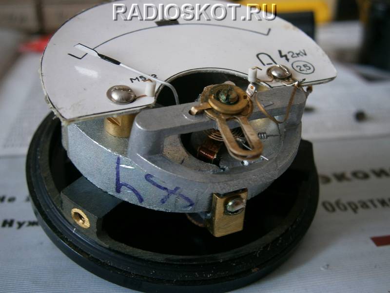
If you do not know the characteristics of the indicator, then to find out what current it is at, simply connect it to an ohmmeter first at a known current (where the marking is indicated) and remember the percentage of scale deviation.

And then connect an unknown pointer device and by the deflection of the pointer it will become clear what current it is designed for. If a 50 µA indicator gives a complete deviation, and an unknown device at the same voltage gives a half deviation, then it is 100 µA.

For clarity, I assembled a surface-mounted RF signal detector and measured the radiation from a freshly assembled FM radio microphone.

When the transmitter circuit is powered from 2V (severely shrunken crown), the detector needle deviates by 10% of the scale. And with a fresh 9V battery - almost half.

Are you fed up with your neighbors' loud music or just want to make some interesting electrical equipment yourself? Then you can try to assemble a simple and compact electromagnetic pulse generator that is capable of disabling electronic devices nearby.
An EMR generator is a device capable of generating a short-term electromagnetic disturbance that radiates outward from its epicenter, thereby disrupting the operation of electronic devices. Some EMR bursts occur naturally, for example in the form of electrostatic discharge. There are also artificial EMP bursts, such as a nuclear electromagnetic pulse.
This material will show you how to assemble a basic EMP generator using commonly available items: a soldering iron, solder, a disposable camera, a push-button switch, insulated thick copper cable, enameled wire, and a high-current latched switch. The presented generator will not be very powerful in terms of power, so it may not be able to disable serious equipment, but it can affect simple electrical appliances, so this project should be considered as a training project for beginners in electrical engineering.
So, first, you need to take a disposable camera, for example, Kodak. Next you need to open it. Open the case and locate the large electrolytic capacitor. Do this with rubber dielectric gloves to avoid getting an electric shock when the capacitor is discharged. When fully charged, it can show up to 330 V. Check the voltage on it with a voltmeter. If there is still a charge, remove it by shorting the capacitor terminals with a screwdriver. Be careful, when shorted, a flash will appear with a characteristic pop. After discharging the capacitor, remove the circuit board it is mounted on and locate the small on/off button. Unsolder it, and in its place solder your switch button.

Solder two insulated copper cables to the two terminals of the capacitor. Connect one end of this cable to a high current switch. Leave the other end free for now.

Now you need to wind the load coil. Wrap the enamel-coated wire 7 to 15 times around a 5cm diameter round object. Once the coil is formed, wrap it with duct tape to make it safer to use, but leave two wires protruding to connect to the terminals. Use sandpaper or a sharp blade to remove the enamel coating from the ends of the wire. Connect one end to the capacitor terminal and the other to a high-current switch.

Now we can say that the simplest electromagnetic pulse generator is ready. To charge it, simply connect the battery to the corresponding pins on the capacitor circuit board. Bring some portable electronic device that you don't mind to the coil and press the switch.

Remember not to hold down the charge button while generating EMP, otherwise you may damage the circuit.
This interesting device allows you to hear the world of electromagnetic radiation that surrounds us. It converts high-frequency vibrations of radiation generated by a variety of electronic devices into an audible form. You can use it near computers, tablets, mobile phones, etc. Thanks to it, you will be able to hear truly unique sounds created by operating electronics.
Schematic diagram
The scheme assumes the implementation of this effect with the smallest possible number of radioelements. Further improvements and corrections are at your discretion. Some part values you can tailor to your needs, others are permanent.
Build process
Assembly requires the use of a breadboard of at least 15 x 24 holes, and special attention is paid to the layout of the elements on it. The photographs show the recommended location of each of the radio elements and what connections to make between them. Jumpers on a printed circuit board can be made from cable fragments or cut off legs from other elements (resistors, capacitors) that remain after their installation.

First you need to solder the coils L1 and L2. It's good to move them away from each other, which will give us space and increase the stereo effect. These coils are the key element of the circuit - they act like antennas that collect electromagnetic radiation from the environment.

After soldering the coils, you can install capacitors C1 and C2. Their capacitance is 2.2 μF and determines the lower cutoff frequency of sounds that will be heard in the headphones. The higher the capacitance value, the lower the sounds reproduced in the system. Most powerful electromagnetic noise lies at 50 Hz, so it makes sense to filter it out.
Next, we solder 1 kOhm resistors - R1 and R2. These resistors, together with R3 and R4 (390 kOhm), determine the gain of the operational amplifier in the circuit. Voltage inversion is not particularly important in our system.
The virtual mass is resistors R5 and R5 with a resistance of 100 kOhm. They are a simple voltage divider, which in this case will divide the 9 V voltage by half, so from a circuit point of view the m/s is powered by -4.5 V and +4.5 V in relation to the virtual ground.
You can put any operational amplifier with standard pins into the socket, for example OPA2134, NE5532, TL072 and others.

We connect the battery and headphones - now we can use this acoustic monitor to listen to electromagnetic fields. The battery can be glued to the board with tape.
Additional features
What can be added to increase functionality? Volume control - two potentiometers between the output from the circuit and the headphone jack. Power switch - now the circuit is on all the time until the battery is disconnected.

During testing, it turned out that the device is very sensitive to the field source. You can hear, for example, how the screen on your mobile phone is updated, or how beautifully the USB cable sings while transferring data. When attached to a switched-on loudspeaker, it works like a regular and quite accurate microphone that collects the electromagnetic field of the coil of a working speaker.
Hello, dear friends!
I purchased and tested the functionality of an electromagnetic radiation detector. I ask for a cozy cut :)
Let’s start from afar, I don’t watch TV myself, but when I’m visiting my parents I watch it with one eye, when I talk to my mother. So, by chance, my mother and I watched a piece of a program in which the film crew of the NTV channel “Mysterious Russia” ran to a cemetery with an electromagnetic radiation detector.
The announcer, in a sepulchral voice, said: “Today it is reliably known that increased electromagnetic background can actually negatively affect people. Push them into rash, risky actions and even suicide.” Well, and so on, I don’t remember if they caught ghosts there or anything else, it doesn’t matter now.
I thought it would be a good idea to measure the radiation in the server room, besides, my mother also wanted one. High-voltage power lines inspire horror in many people, or rather the proximity of their residence.
I read on the Internet that there are household sensors for detecting “harmful electromagnetic fields that come from high-voltage lines, television screens, computers, microwave ovens, etc. Experts believe that, starting at a level of 2-3mG, these electromagnetic fields increase the danger of certain diseases (for example, cancer)."
There is a video about such a device, although the price is 2000 rubles, who is too lazy to look for it, here is the link
There is also one for 140,420 rubles, here, but this is for gourmets :)
I sat and looked for Chinese analogues in online stores and came across this copy.
I talked with the seller, begged for a discount as always, this time they gave 20% as for the “first order in your store.”
I paid $13, they sent it and gave me a track. I waited 24 days, here is the track.

The parcel was well packed, sealed, the device was in a separate box, the box was in excellent condition, there was no battery included, this is my own:


I quickly inserted the battery:


I checked the functionality, it beeped and showed numbers on the screen, when brought close to power cables and household appliances, everything is in order, the device works. The controls are very simple: the first red button is to turn on, the second is to freeze the value on the screen.
Almost immediately I decided to take it apart:


I was somewhat confused by the crumpled antenna inside, so I immediately decided to straighten it and run it along the body, making small slits with a stationery knife (as it later turned out, this was not superfluous, because the sensitivity increased significantly):

It is not entirely clear in what units the device measures the electromagnetic field strength, presumably in milligauss (mG). It’s difficult to say for sure, since the device is not certified in Russia and it cannot be used to legally assess the suitability of places of work (it can only be done illegally:)
I measured the voltage near the “high-voltage lines”, the device goes off scale and beeps furiously, but when moving 10 meters away from the line, it quiets down and shows 0. This made my mother very happy, since the house is located far beyond the border of these 10 meters. Although a reinforced concrete 220/380 V power line support with porcelain linear insulators can hardly be called high-voltage.
There are plans to visit my grandfather and measure the background of “harmful fields” in the apartment that interfere with his sleep.
Minuses:
1) No certification in Russia
Pros:
1) Compact size
2) Low price
3) Light weight
This is my first review of such a complex thing. Please don't kick the techies too hard in the face :)
P.S.
I recorded a video of the sensor working without human hands.
In addition to a multimeter, of course, you need to have a special indicator of the electromagnetic field it emits. And it is desirable to assemble a broadband circuit capable of responding to frequencies from FM to GSM without modification. This is exactly the kind of detector we will make. The circuit of this field indicator is a DC op-amp amplifier with a UHF stage and an RF detector. A high-pass filter L1, C2, L2, C3 is installed at the UHF input, which cuts off signals with a frequency below 10 MHz, otherwise the device begins to respond to electrical wiring background and other interference. The RF amplifier is made according to a common emitter circuit; the mode is set by resistor R1 so that the collector VT1 has a voltage equal to half the supply voltage.
Through capacitor C4, the signal is supplied to the diode detector VD1; here it is necessary to use a microwave germanium diode GD402, GD507; diode D9, whose maximum frequency is 40 MHz, cannot be used. The rectified signal is supplied to the input of the op-amp through filter L3, L4, C6, C7, which prevent the RF component from entering the input of the op-amp. The operational amplifier operates from a single-supply supply, so for its normal operation, using a divider on R4; R5 created an artificial “midpoint”. The gain of the microcircuit is determined by the ratio R6/R8 at small input signals. When the voltage at pin 6 of the microcircuit increases to 0.6 volts, diode VD2 opens and resistor R7 is connected to the feedback circuit of the amplifier, which reduces the gain and makes the scale of the device linear.
As an op-amp, you can use 140UD12 or 140UD6. If you use UD6, resistor R9 must be removed from the circuit. Resistor R10 sets the device scale to 0. VT1 is a microwave transistor, for example KT399. Coil L1 - 8 turns, 0.5 wires on a 5 mm mandrel, L2 - 6 turns of the same wire. Chokes L3, L4 50 - 100 μH each.

The following circuit is a modified design; the use of an additional op-amp made it possible to eliminate the resistor voltage divider and improve the characteristics of the device. The circuit is very simple and should not cause difficulties in manufacturing and configuration.

This design is capable of detecting:
- Radio microphone V Pit=3 V. F=93 MHz - 4 meters.
- Radio microphone, single transistor, Vpit=3 V. F=420 MHz - 3 meters.
- Radio microphone Vpit=3 V. F=860 MHz - 80 cm.
- Chinese TV camera Vpit=9V. F=1200 MHz. - 4 meters.
- Mobile phone, during transmission - up to 7 meters.