DIY directional Wi-Fi antenna. Do-it-yourself “double” Bi-Quad WiFi antenna
Setting up Wi-Fi networks demonstrates quite a lot of nuances. I came across someone trying to share the Internet with home users. One computer is connected to the provider via cable. An access point mode is created, a security protocol and a password are selected. Home users use the Internet in parallel. The technique does not work, thanks to the provider using a private line. The exit is located. The obstacles that stand between people and high-speed Internet are powerless to prevent a homemade Wi-Fi antenna from improving signal reception and transmission; communication range and speed naturally increase.
Purpose of homemade Wi-Fi antennas
Antennas adorn many devices. Let's list:
- Tablet.
- IPhone.
- Laptops.
- Wi-Fi modems.
- Wi-Fi routers, access points.
- Cell towers.
A homemade antenna for a Wi-Fi adapter will expand the capabilities of electronics. The access point is distinguished by its ability to transmit the signal omnidirectionally. The power spreads, filling the azimuths. By supplementing the access point with a special external purchased, homemade antenna, it can impart directional properties to the radiation. Will increase the range of reliable reception in the selected azimuth.
Stop breaking your smartphones by connecting an external antenna and assemble it yourself for an access point. Most antennas sold in stores have a circular radiation pattern, radiating equally, omnidirectionally, dividing the power in azimuths.
Powerful homemade Wi-Fi antennas have a much smaller field of view and will provide more reliable reception in some cases. Reflector-equipped devices have a radiation pattern with one central lobe. Remove the reflector and you get a figure eight. There will be a dead zone in the plane of the emitter; there will be no signal. A homemade antenna for a Wi-Fi router is unable to receive directional signals. The access point installation scheme is as follows:
- The device is connected to a computer (electrical network).
- The channel is selected.
- The setting is carried out at full power.
- The protocol type is selected.
- The password and network name are set.
People walk around happy with the new accessible point. Let's take a closer look at the process; let's take a moment to grab a soldering iron and pliers. Like a transmitter, a radio-electronic device, an antenna, or a router have a certain peak of capabilities in the middle of the range. For example, on 2.4 GHz there are often 14 channels. The power of the transmitted signal is higher in the middle, for example, the sixth channel. Although each line occupies 22 MHz of the spectrum, the measurement is carried out at a field level of 0.707 (√2/2) maximum on both sides of the carrier frequency.
For reference. Determined by the modulation type, sometimes only the pilot signal remains, one band. Rectangular pulses, computer signals are just like that, have a pronounced maximum, a bunch of side lobes. As a result, the spectrum width of the real signal is infinity. The cyclic voltage band is limited, to which the process emitted by the Wi-Fi protocol does not come close.
A homemade omnidirectional Wi-Fi antenna is not the best option. Nothing will change. A homemade directional Wi-Fi antenna is better; we will make it from wire, foil PCB, or copper tube. They are so sensitive. Transmitted and received powers are concentrated in a narrow sector. It will improve the quality of transmission by carefully positioning users and the access point. You can judge how important the arrangement is by one curious case:
- The office called a technician. They said: between 12.00 and 14.00 the access point collapses. The technician took out a special device for estimating occupied frequencies and began the study. Similar programs are provided by the Android OS of smartphones. Use by selecting a channel before installation. Conduct research throughout the day for several days in a row, avoiding incidents. We bring to light what the master discovered: the neighboring office, separated by a wall, painted lunch. The workers took turns using the microwave (using the 2.4 GHz frequency). Poor insulation of household appliances and lack of grounding allowed the radiation to expose narrow-band interference at the frequency of the magnetron. The solution to the problem turned out to be simple: the access point was moved to the opposite end of the office.
If they had at hand a simple homemade Wi-Fi antenna from a beer can with a reflector, the heroes might not have known that there was a powerful source of harmful radiation next door. The reflector gives the access point directionality and will dampen the radiation coming from behind the wall. Another advantage of directional antennas, which we will make with our own hands today. By the way, when buying a microwave, try to determine safety. You need to plug the device into a grounded outlet, put your cell phone in the working compartment, close the door, and dial the number. The signal passes - harmful radiation from the magnetron will come out. Avoid sitting nearby. Let's discuss how to make a homemade Wi-Fi antenna.

DIY directional Wi-Fi antenna
Tools you will need:
- Soldering iron (solder, rosin, stand).
- Pliers.
- Small flathead screwdriver.
- Vernier caliper, ruler.
- Drill with a drill for a copper pipe.
Materials you will need:
- A piece of foil double-sided PCB as a reflector.
- Copper wire with a diameter of 1.2 mm and a length of 30 cm (only 26 cm of which will be needed).
- The RK-50 cable is not too long so as not to dampen the signal.
- A piece of copper tube 10 cm long for the RK-50 cable to pass inside.
Let's start with a copper tube. We saw through one end by 1.5 mm, removing two-thirds of the wall. The antenna will be soldered to the remaining piece. We create a bi-square contour with a side of 30.5 mm from wire. The size was selected based on the 2.4 GHz band setting condition.

In a similar way, you can make any antenna with a horizontal or vertical polarization signal. Including television. A homemade Wi-Fi antenna is suitable for a tablet, phone, or modem. If you know where to connect.
Please note that the side of the squares is given according to the middle section of the wire. Between the nearest edges there will be 30.5 - 1.2 = 29.3 mm. You can use it. We begin to bend, finding the middle. We use the edge of the ruler as a support and determine the state when the cut begins to balance. We make a bend of 90 degrees, this will be the point where the central core of the RK-50 will connect. We bend the wire, getting a “square eight”, both ends should return strictly symmetrically. We cut it a couple of millimeters short of the initial bend. We tin the ends and put the figure eight aside.
We mark the middle of the PCB and drill a hole so that the copper tube barely fits in. We cheat both sides. We take a copper tube and tin the outer edge of the thin wall left by the first stage. The figure eight is 1.5 cm away from the reflector. We tin the tube in a circle, with the rim at the specified distance from the edge (without taking into account the thin wall). Solder the tube to the board, preferably at an angle of 90 degrees. We place both ends of the figure eight on a thin wall so that the initial bend does not touch the tube. We orient the figure eights parallel to the larger side of the PCB at a distance of 1.5 cm. Now the reflector is grounded.
The RK-50 cable is pulled inside, the screen is placed on the copper tube, the core is placed on the initial bend of the figure eight. We mount the connector on the opposite end, simply solder the cut to the required contacts of the modem, telephone, or any other device. Let's start the test. The figure eight must be mounted vertically for horizontal polarization. If it works, we find silicone sealant that is not afraid of frost and precipitation, and fill the place where the cable exits with the antenna with a good layer. After hardening, the antenna will successfully withstand rain.
If you replace the wire with a thick conductor PV1 of a sufficiently large cross-section (2.5 mm 2), we will strip the braid at the point of initial bending and at the ends. A homemade Wi-Fi antenna for a laptop will be protected against bad weather. Today, heat-shrinkable materials are produced. The heated film tightly wraps the product, protecting it from the vagaries of bad weather.
We make a Wi-Fi antenna with our own hands.
Wi-Fi wireless data technology has taken over the world. Almost every house and every apartment has devices that support this standard. For example, routers (routers) “distributing” a Wi-Fi signal throughout an apartment or house.
Unfortunately, the power of these devices is not always sufficient to provide more or less acceptable signal strength in all rooms and rooms of apartments, and especially houses. For example, the TP-LINK router I use is located in a corner room and provides the signal level at almost the minimum limit for the rooms farthest from it. It’s not surprising - the signal has to break through four walls.
What to do in such cases in order to increase the level of the router’s Wi-Fi signal to acceptable values? That's right - make your own Wi-Fi antenna.
The network is full of designs for such antennas. More effective are those antennas that can be connected instead of the standard whip antennas of routers.
This option is not suitable for me. The antenna of my router is not removable, I don’t want to climb inside the router to solder the cable of a homemade antenna - the router is still under warranty.
Therefore, we find another option - an antenna attachment.
This antenna attachment is simply put on the standard whip antenna of the router. There is no need to solder anything anywhere.
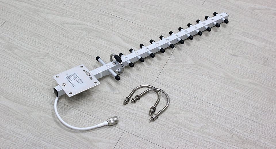
The attachment antenna is a six-element “wave channel” and has directional properties. Provides maximum gain in the direction coinciding with the longitudinal axis of the antenna. In addition, the back lobe of radiation is suppressed (decreased) to some extent. The antenna has five director elements and one reflector.
Antenna sketch:

For the manufacture of the traverse, fiberglass laminate with a thickness of 2 mm was selected.
The standard whip antenna of my TP-LINK router has an irregular geometric shape in cross section, in full accordance with the perverted tastes of modern design designers))).
The completed traverse looks like this: 
The radiating elements of the antenna attachment are made of copper wire in enamel insulation with a diameter of 0.96 mm. The diameter of the wire is quite critical and must be within 0.8...0.95 mm, otherwise the antenna parameters will change and the antenna attachment will be tuned to frequencies different from those of the Wi-Fi range.
The lengths of the radiating elements must also be maintained with an accuracy of +/- 0.5 mm. The same applies to the distance between elements.
Antenna elements: 
To install radiating elements, holes with a diameter slightly larger than the diameter of the wire elements are drilled in the fiberglass traverse. I fixed the wire elements with small drops of cyanoacrylate glue.
The assembled antenna attachment looks like this: 
This is what the Wi-Fi antenna looks like installed on the standard antenna of the router: 

To achieve maximum efficiency of this Wi-Fi antenna, a small adjustment is required: the Wi-Fi antenna should be placed at the point where there is maximum RF current from the standard whip antenna of the router.
To do this, you need to move the Wi-Fi antenna in height, starting from the upper tip of the router’s standard antenna. The effectiveness can be checked either with some kind of field strength indicator, or by checking the signal strength with a tablet, smartphone, etc. in the rooms farthest from the router.
In my case, the most efficient Wi-Fi antenna works when installed 25 mm below the top tip of the standard router pin. This antenna gave an increase of one notch on the signal strength indicator in those rooms where the signal was at its minimum.
The Wi-Fi wireless information transmission system (the abbreviation does not stand for it, it was invented as a marketing ploy) is one of the pillars of modern high-tech society. With its help, not only the Internet is distributed, but also, for example, signals from video cameras. In its physical essence, it is radio communication at a frequency of 2.4 GHz and obeys all the laws of radio wave propagation.
Therefore, if your tablet or laptop refuses to communicate with the router due to interfering walls and ceilings, you can try making a signal amplifier yourself. This is a directional antenna in the centimeter range. Its design can be pin, frame, spiral or zigzag. In this article we will try, without delving into the jungle of the theory of antenna-feeder devices, to explain to you how to make an antenna from scrap materials that will be no worse than those sold in the store.
Before you start choosing the type of antenna and putting your grandiose plans into practice, you should familiarize yourself with the fundamental laws of the theory of antenna-feeder devices. There are two of them:
- Wavelength, which determines the size of the device.
- Gain. The most interesting point, which makes it possible to detect a weak radio signal over long distances, is exactly why we are taking on this matter.
The magnetic field strength diagram of any radio signal has the shape of a sinusoid. The distance between the first and third points where it intersects the x-axis is called the wavelength.
The frequency rating is the number of oscillations per second. Since a radio signal travels at the speed of light, the wavelength in meters will be equal to the result of its division by the frequency. For low frequency (most common) Wi-Fi range: 299792458 / 2.4 = 12.5 cm.
Remember this value, since all dimensions of the future antenna will be calculated as its fractional parts.
Gain is a conditional value that shows how many times the output signal at the terminals of a directional antenna is greater than that of an omnidirectional antenna. Moreover, this ratio is calculated as a decimal logarithm and is denoted dB - decibel. Omnidirectional is one for which the position relative to the radio signal source is indifferent. These are used in mobile phones and tablets, since this is, firstly, assumed by the terms of use, and, secondly, determined by the small size of the devices.
 The directional properties of an antenna appear if its length is equal to half the wavelength. For Wi-Fi it is 6.25 cm. Its spatial radiation pattern is a torus - a donut, perpendicular to the antenna axis. The gain in this case is equal to two decibels, that is, 1.58 times. Such half-wave dipoles allow you to increase the range by ten meters, which is already good for reliable signal reception in your apartment.
The easiest way to boost a signal
 If you take a ruler and measure the length of the whip antenna of your home router, it will turn out that its length is from 10 to 12 cm. They don’t make it longer because in a pin whose size is larger than the wavelength, the internal resistance increases significantly and the signal goes out instead of being amplified. This increase in size leads to a narrowing of the thickness of the donut pattern and a slight increase in the power density of the emitted signal. Shielding the transmitting antenna on one side has a much greater effect.
The screen allows you to concentrate the radiation of the router in the direction you need. For example, if it is located against a wall, then there is no reason to transmit the Wi-Fi signal to neighbors or to the street. Its installation increases the gain of the transmitting antenna to 3 dB, that is, twice. Which actually reflects the physical essence of the matter, because you reoriented half of the uselessly directed signal in the right direction.
The trick is how far from the router antenna to place the screen. According to the laws of radio signal propagation, it should be equal to 1/8 of the wavelength. For Wi-Fi it is 1.56 cm.
It can be a sheet of iron (cut beer or tin can), a compact disc or thick foil. It is best to make the design in the form of a stand for the router, with the screen placed perpendicular to it. You can achieve the result experimentally by moving the signal source closer or further from the screen by millimeter. The network level display interface will help you.
The advantage of this method is its simplicity, and also the fact that you do not need an antenna for the tablet. That is, you don’t have to open it or find ways to connect additional equipment. The disadvantage is the short range of signal reception.
Directional Antennas
A powerful antenna - with a gain of 10 dB - is needed if the expected reception range is at least 50 meters. In this case, highly directional antennas are used. For example, zigzag or spiral.
Zigzag
 It is called both the Kharchenko antenna, after the radio amateur who proposed such a design in 1961, and the biquad antenna, for its characteristic shape. It is constructed from a conductor two waves long of the intended signal. For Wi-Fi, this value is 25 cm. It bends in the form of two squares with a side of ¼ wavelength - 3.125 cm. The point of their articulation is detachable. Usually it is attached to a dielectric plate to ensure rigidity so that there is no overlap between the soldering points of the central core of the coaxial cable to one branch and the screen to another.
The biquad antenna has a gain of 8 dB in the basic version, and about 12 dB if a screen is installed, which can be a CD, foil, or sheet of metal. The distance to it from the plane of the conductor bent into two squares is 1.56 meters - an eighth of the wavelength. The design is convenient in that the extreme points of the squares along the axis have zero potential, so they can be attached to the screen with anything, including metal wire, providing good rigidity.
To ensure the required gain, it is placed vertically. In the horizontal direction, its directional properties are no better than those of a half-wave dipole. The receiving axis is located perpendicular to the plane of the figured conductor.
Coordination with the cable is not required; it connects directly to the conductor.

The spiral antenna was invented in the late 40s of the last century by the American radio engineer J. Kraus. Very simple in design, it provides signal amplification up to 20 dB (100 times) and is used in all bands, starting from VHF. Reception range up to 2 km within line of sight. It consists of several turns of a conductor twisted into a spiral.
The diameter of the spiral turn is equal to the wavelength. Therefore, when creating the frame of a homemade antenna of this type, a piece of sewer plastic pipe with a diameter of 40 mm is ideal. They are in every hardware store.
The spiral is sparse. The distance between turns is ¼ wavelength. The longer it is, the sharper the radiation pattern and the higher the gain. For a distance of three kilometers, it is enough that the total length is equal to three wavelengths - 36 cm.

The conductor used is a household single-core copper wire with a cross-section of 2.5 mm 2 - diameter 1.5 mm. The insulating shell cannot be removed. It is evenly glued to the base pipe.
The screen is made of any sheet material; its position does not depend on the wavelength multiplicity.
The antenna requires coordination with the power cable. For this, a piece of copper sheet in the form of a right triangle with legs 71 and 17 mm long is used. It is glued to the pipe so that the slope of the hypotenuse follows the slope of the coil. The central core of the cable is soldered to the angle opposite the straight line (at the intersection of the hypotenuse and the short leg). The braid is soldered to the screen.
The disadvantage of the antenna is that it is somewhat bulky and somewhat difficult to position - the direction towards the router must be maintained within a few degrees.
Connection
After assembling the Wi-Fi antenna, you will definitely have a question about how to connect it. Typically, laptops and tablets do not have connectors for this. To solve the problem, buy a remote antenna for your mobile phone with a magnetic adapter that sticks to the body of the device. Disconnect the cable from the magazine device and use it for your own purposes. Of course, in this case, signal loss will increase, and the actual reception range will be slightly lower than expected. But you don’t have to open the computer and manipulate its circuitry.
A carefully assembled Wi-Fi antenna will help you be within the coverage area of free networks and not give up Internet services even during a trip out of town.
The wireless network standard is still powerless to displace mobile communication technology; the explanation is simple: the range is relatively short. Of course, some other features were noticed - difficulties in identification, a large amount of energy consumed, the key point in distance. Let's consider whether it is possible to make a directional Wi-Fi antenna yourself.
Posing the question is scary. It's simple, just take the trouble to master a couple of terms. Popov, inventing radio, knew little about how electromagnetic waves propagate. There were simply two antenna wires - the first one radiated, the second received. It gradually became clear: the nature of the propagation of waves by the atmosphere is determined, in addition to the frequency (wavelength), by weather conditions.
The state immediately took over the optimal ranges, providing military needs and communications between organizations. The remainder was given to broadcasting and radio amateurs.
In addition to the conditions for energy propagation, antennas play an important role in organizing a stable channel. If nothing can be done with the wavelength ranges - they are given a priori, it is possible to conduct experiments with antennas.
The antennas used by Popov are omnidirectional. The signal strength is evenly distributed across all cardinal directions. Engineers quickly discovered this fact and began to look for ways to correct the deficiency.
Many solutions were found. In the simplest case, the emitter is placed at the focal point of a hyperbolic dish. It turns out to be a satellite television antenna. The effect is similar to optical: rays falling at right angles onto the opening of a truncated hyperboloid are collected by a focal point. The plate is called a reflector - from Latin - reflector. Transmitting and receiving antennas placed in focus work more efficiently than an omnidirectional Wi-Fi antenna.
Directional pattern, gain
A person far from engineering calculations asks: the rays are concentrated at a focus, amplifying the power of the incoming signal many times over, what does the transmitters have to do with it? The antenna's reception and transmission properties are identical. Characterized by a directional pattern. The curve, either circular or drawn in a rectangular coordinate system, shows how much power is emitted in a given direction.
Popov's antennas had a diagram similar to a circular one. A directional Wi-Fi antenna works differently: a long peak is formed in front. The height is so huge that it has to be expressed in decibels - relative units, otherwise you will have to draw a thin needle in the middle and even zero horizontal lines on the sides. Invisible.
The last term to become familiar with is antenna gain. The ratio of the peak power of the fundamental direction to the power radiated under similar conditions by an omnidirectional antenna. The parameter is calculated in hundreds of units and is expressed in decibels (20 dB).
It's easy to see why a directional Wi-Fi antenna is so effective - it amplifies the signal many times over. The home-made models discussed below do not have such impressive indicators; the 6 dB gain brings more than the 2 dB of the standard antenna that comes with the router.
The simplest options for homemade Wi-Fi antennas
Method 1
The SLTV master class, through the mouth of a blonde presenter, told about two well-known ways to make a router antenna directional. The main idea is expressed intermittently - a pin sticking out of a small box is equipped with a reflector. There is no need to talk about placing the emitter into focus; zero effect is expected.
The simplest way is to equip the antenna with a laser disk with the shiny side facing out. The mechanics are simple: the aluminum layer of a printed, recorded product perfectly reflects any wavelength, within reasonable limits.
The directional pattern of the pin will change sharply - on the contrary, perpendicular to the disk, a pronounced maximum will appear. You will have to position the spire horizontally, with the top facing the consumers, or most of the energy will go up. The blonde, smiling sweetly, said: in addition to the indicated method, there is a more advanced method to make a directional antenna with your own hands.
Method 2
You will need an empty, dried beer can and another similar one. The bottom is cut off, the neck is separated by a perimeter, leaving a narrow isthmus a couple of centimeters wide.
The sidewall is cut straight along, diametrically opposite to the isthmus. The walls are leveled. Now, through the egg-shaped hole from which the bottle opener was torn off, the reflector is put on the antenna.
The rounded wall resembles a paraboloid plate with cut edges. The advantage of the solution: you can rotate the reflector in a circle, adjusting the desired direction.
The gain will have to be adjusted with skillful hands, sensitively selecting the position of the reflector. The Wi-Fi antenna is now directional.

Alternative methods
In addition to the router pin, similar actions can be performed with a low-power Wi-Fi modem (flash drive). You will need a USB extension cable. Strengthened by the knowledge gained (see the first two methods), we will make a reflector, plus a protective casing from:
- boxes for laser discs with one disc at the bottom;
- a flat metal sieve with folding edges and a small plastic jar;
- a large wire sieve in the shape of a hemisphere/truncated hyperboloid;
- a homemade woven structure made from a thin cable with a frame made of a metal rod.
The flash modem is placed as close to the focus as possible, the cord goes through a slot in the center of the reflector to the personal computer.
Reception will undoubtedly improve when you have a DIY Wi-Fi antenna. An undoubted advantage of the design is the possibility of arbitrary orientation of the main beam of the radiation pattern. Usually there is one remote signal source/receiver; a modem with a reflector should be deployed there.
Lyrical digression
Beer cans are used to aid microwave spectrum designers. They resemble waveguides coated with aluminum on the inside. Not surprisingly, radio amateurs often try to adapt the signal to the needs of broadcast catching.
This case is typical. Children's stores in the USSR were filled with... sleds. Things went on smoothly until the local engineers realized: the products lying on the shelves were parabolic antennas; the clerks gave the items rejected by military acceptance to the sellers. By the end of the day, the sled was bought back.

The digression has the sole purpose of showing: a Wi-Fi antenna can be easily made from scrap materials. A rectangular waveguide cannot be manufactured; a round one is made by a brewery.
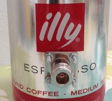
Beer can antenna
To make the jar a decent 2.4 GHz reflector, take the trouble to carefully cut off the bottom. The emitter will be a quarter-wave vibrator, formed by a piece of thin (1.5 mm) wire about 5 cm long. 1.5 cm will be recessed by the n-connector, 30 mm should protrude above the inner wall.
A hole for the connector is cut in the lower part of the side wall at a distance from the bottom determined by the diameter of the can. For 90 mm the indentation will be 51 mm, for 80 - 70 mm. You will have to select the distance empirically, having ruined many excellent beer cans.
Further actions are very simple - the vibrator is strengthened perpendicular to the inner wall, protruding by 30 mm. The radiation pattern is 30 degrees wide. Polarization is important: two banks with emitters directed perpendicular to each other will refuse to work together.
By the way, a 30 mm long wire pin is an omnidirectional Wi-Fi antenna, made with your own hands from scrap material, designed to master the 2.4 GHz frequency. Handy materials are great! It remains to supplement the pin with counterweights, which play the role of the ground of the receiving device.
The model will refuse to catch frequencies of 900 MHz, 5 GHz; in addition, when choosing a tin can, give preference to containers with a diameter of 7 - 10 cm. Dimensions that fall outside the range greatly reduce the gain of the product.
Connect the assembled device
In previous cases it’s simple. Take a Wi-Fi modem, a connected antenna, and surround it with a reflector. A beer can and a quarter-wave vibrator are not very different in terms of docking: when you open the flash drive modem, you will find contacts inside for connecting the can. There are antenna slots in the routers, where beer products will fit perfectly.
Naturally, an aluminum or copper product can replace a container for a strong drink. The dimensions are chosen to be similar. Good luck with your design.
A weak WiFi signal is a pressing problem for residents of apartments, country houses and office workers. Dead zones in a WiFi network are typical for both large rooms and small apartments, the area of which even a budget access point can theoretically cover.
The range of a WiFi router is a characteristic that manufacturers cannot clearly indicate on the box: the WiFi range is influenced by many factors that depend not only on the technical specifications of the device.
This material presents 10 practical tips that will help eliminate the physical causes of poor coverage and optimize the range of your WiFi router; you can easily do it yourself.
The radiation from the access point in space is not a sphere, but a toroidal field, shaped like a donut. In order for WiFi coverage within one floor to be optimal, radio waves must propagate in a horizontal plane - parallel to the floor. For this purpose, it is possible to tilt the antennas.

The antenna is a donut axis. The angle of signal propagation depends on its inclination.
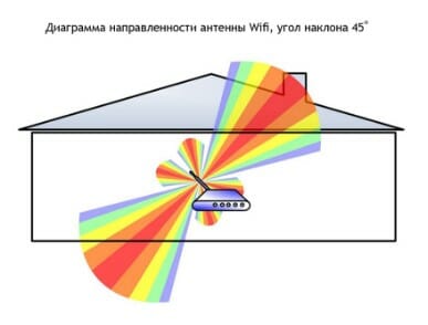
When the antenna is tilted relative to the horizon, part of the radiation is directed outside the room: dead zones are formed under the “donut” plane.

A vertically mounted antenna radiates in a horizontal plane: maximum coverage is achieved indoors.
On practice: Mounting the antenna vertically is the easiest way to optimize indoor WiFi coverage.
Place the router closer to the center of the room
Another reason for the occurrence of dead zones is the poor location of the access point. The antenna emits radio waves in all directions. In this case, the radiation intensity is maximum near the router and decreases as it approaches the edge of the coverage area. If you install an access point in the center of the house, the signal will be distributed throughout the rooms more efficiently.
A router installed in a corner transmits some of the power outside the house, and distant rooms are at the edge of the coverage area.

Installation in the center of the house allows you to achieve even distribution of the signal in all rooms and minimize dead zones.
In practice: Installing an access point in the “center” of the house is not always feasible due to the complex layout, lack of sockets in the right place, or the need to lay a cable.
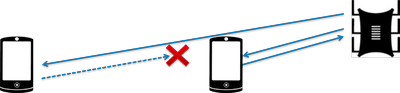
Provide direct visibility between the router and clients
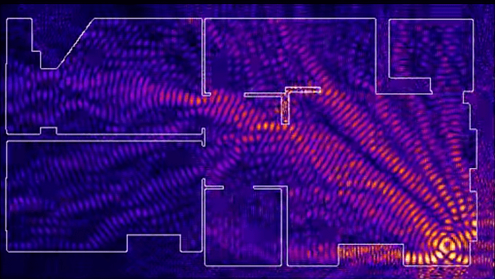
WiFi signal frequency is 2.4 GHz. These are decimeter radio waves that do not bend well around obstacles and have low penetrating ability. Therefore, the range and stability of the signal directly depend on the number and structure of obstacles between the access point and clients.

Passing through a wall or ceiling, an electromagnetic wave loses some of its energy.
The amount of signal attenuation depends on the material the radio waves travel through.
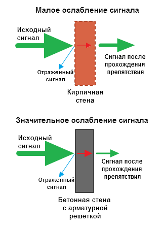

*Effective distance is a value that determines how the radius of a wireless network changes in comparison with open space when a wave passes an obstacle.
Calculation example: WiFi 802.11n signal propagates under line-of-sight conditions over 400 meters. After overcoming the non-permanent wall between the rooms, the signal strength decreases to 400 m * 15% = 60 m. The second wall of the same type will make the signal even weaker: 60 m * 15% = 9 m. The third wall makes signal reception almost impossible: 9 m * 15 % = 1.35 m.
Such calculations will help calculate dead zones that arise due to the absorption of radio waves by walls.
The next problem in the path of radio waves: mirrors and metal structures. Unlike walls, they do not weaken, but reflect the signal, scattering it in arbitrary directions.
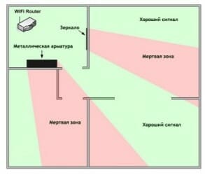
Mirrors and metal structures reflect and scatter the signal, creating dead zones behind them.

If you move interior elements that reflect the signal, you can eliminate dead spots.
In practice: It is extremely rare to achieve ideal conditions when all gadgets are in direct line of sight to the router. Therefore, in a real home, you will have to work separately to eliminate each dead zone:
- find out what interferes with the signal (absorption or reflection);
- think about where to move the router (or piece of furniture).
Place the router away from sources of interference
The 2.4 GHz band does not require licensing and is therefore used for the operation of household radio standards: WiFi and Bluetooth. Despite the low bandwidth, Bluetooth can still interfere with the router.

Green areas - stream from the WiFi router. Red dots are Bluetooth data. The proximity of two radio standards in the same range causes interference, reducing the range of the wireless network.
The magnetron of a microwave oven emits in the same frequency range. The radiation intensity of this device is so high that even through the protective screen of the furnace, the magnetron radiation can “illuminate” the radio beam of the WiFi router.

Microwave oven magnetron radiation causes interference on almost all WiFi channels.
On practice :
- When using Bluetooth accessories near the router, enable the AFH parameter in the settings of the latter.
- The microwave is a powerful source of interference, but it is not used very often. Therefore, if it is not possible to move the router, then you simply won’t be able to make a Skype call while preparing breakfast.
Disable support for 802.11 B/G modes
WiFi devices of three specifications operate in the 2.4 GHz band: 802.11 b/g/n. N is the newest standard and provides greater speed and range compared to B and G.

The 802.11n (2.4 GHz) specification provides greater range than legacy B and G standards.
802.11n routers support previous WiFi standards, but the mechanics of backward compatibility are such that when a B/G device appears in the N-router's coverage area - for example, an old phone or a neighbor's router - the entire network is switched to B/G mode. Physically, the modulation algorithm changes, which leads to a drop in the speed and range of the router.
In practice: Switching the router to “pure 802.11n” mode will definitely have a positive effect on the quality of coverage and throughput of the wireless network.
However, B/G devices will not be able to connect via WiFi. If it is a laptop or TV, they can be easily connected to the router via Ethernet.
Select the optimal WiFi channel in the settings
Almost every apartment today has a WiFi router, so the density of networks in the city is very high. Signals from neighboring access points overlap each other, draining energy from the radio path and greatly reducing its efficiency.
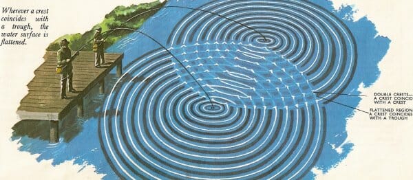
Neighboring networks operating at the same frequency create mutual interference, like ripples on the water.
Wireless networks operate within a range on different channels. There are 13 such channels (in Russia) and the router switches between them automatically.
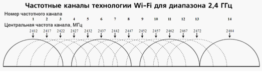
To minimize interference, you need to understand which channels neighboring networks operate on and switch to a less loaded one.
Detailed instructions for setting up the channel are provided.

In practice: Selecting the least loaded channel is an effective way to expand the coverage area, relevant for residents of an apartment building.
But in some cases there are so many networks on the air that not a single channel provides a noticeable increase in WiFi speed and range. Then it makes sense to turn to method No. 2 and place the router away from the walls bordering neighboring apartments. If this does not bring results, then you should think about switching to the 5 GHz band (method No. 10).
Adjust the router transmitter power
The power of the transmitter determines the energy of the radio path and directly affects the range of the access point: the more powerful the beam, the further it hits. But this principle is useless in the case of omnidirectional antennas of household routers: in wireless transmission, two-way data exchange occurs and not only clients must “hear” the router, but also vice versa.
Asymmetry: the router “reaches” a mobile device in a distant room, but does not receive a response from it due to the low power of the smartphone’s WiFi module. The connection is not established.
In practice: The recommended transmitter power value is 75%. It should be increased only in extreme cases: turning the power up to 100% not only does not improve the quality of the signal in distant rooms, but even worsens the stability of reception near the router, since its powerful radio stream “clogs” the weak response signal from the smartphone.
Replace the standard antenna with a more powerful one
Most routers are equipped with standard antennas with a gain of 2 - 3 dBi. The antenna is a passive element of the radio system and is not capable of increasing the flow power. However, increasing the gain allows you to refocus the radio signal by changing the radiation pattern.

The higher the antenna gain, the further the radio signal travels. In this case, the narrower flow becomes similar not to a “donut”, but to a flat disk.

There is a large selection of antennas for routers with a universal SMA connector on the market.


In practice: Using an antenna with high gain is an effective way to expand the coverage area, because simultaneously with the signal amplification, the sensitivity of the antenna increases, which means the router begins to “hear” remote devices. But due to the narrowing of the radio beam from the antenna, dead zones appear near the floor and ceiling.
Use signal repeaters
In rooms with complex layouts and multi-story buildings, it is effective to use repeaters - devices that repeat the signal from the main router.


The simplest solution is to use an old router as a repeater. The disadvantage of this scheme is that the throughput of the child network is half as much, since along with client data, the WDS access point aggregates the upstream flow from the upstream router.
Detailed instructions for setting up a WDS bridge are provided.

Specialized repeaters do not have the problem of reducing bandwidth and are equipped with additional functionality. For example, some Asus repeater models support the roaming function.

In practice: No matter how complex the layout, repeaters will help you deploy a WiFi network. But any repeater is a source of interference interference. When there is free air, repeaters do their job well, but with a high density of neighboring networks, the use of repeater equipment in the 2.4 GHz band is impractical.
Use 5 GHz band
Budget WiFi devices operate on the 2.4 GHz frequency, so the 5 GHz band is relatively free and has little interference.

5 GHz is a promising range. Works with gigabit streams and has increased capacity compared to 2.4 GHz.
In practice: “Moving” to a new frequency is a radical option, requiring the purchase of an expensive dual-band router and imposing restrictions on client devices: only the latest models of gadgets work in the 5 GHz band.
The problem with WiFi signal quality is not always related to the actual range of the access point, and its solution broadly comes down to two scenarios:
- In a country house, most often it is necessary to cover an area in free air conditions that exceeds the effective range of the router.
- For a city apartment, the range of a router is usually sufficient, but the main difficulty is eliminating dead zones and interference.
The methods presented in this material will help you identify the causes of poor reception and optimize your wireless network without resorting to replacing the router or the services of paid specialists.
Found a typo? Select the text and press Ctrl + Enter