High-frequency generator: overview, features, types and characteristics. High frequency (HF) generator circuits
So, the most main block any transmitter is a generator. How stable and accurate the generator operates determines whether someone can pick up the transmitted signal and receive it normally. There are simply a lot of different bug circuits lying around on the Internet, which use various generators. Now we categorize all this a little.
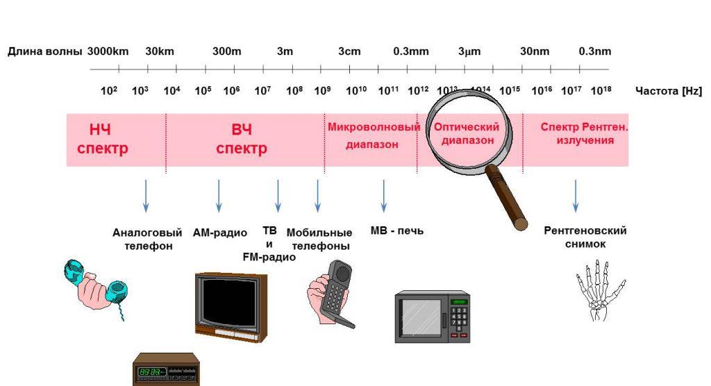
The ratings of the parts of all the given circuits are calculated taking into account the fact that the operating frequency of the circuit is 60...110 MHz (that is, it covers our favorite VHF range).
Classic of the genre - HF generator
The transistor is connected according to a common base circuit. The resistor voltage divider R1-R2 creates an operating point offset on the base. Capacitor C3 shunts R2 at high frequency.
R3 is included in the emitter circuit to limit the current flowing through the transistor.
Capacitor C1 and coil L1 form a frequency-setting oscillatory circuit.
Conder C2 provides the positive feedback (POF) necessary for generation.
Generation mechanism
A simplified diagram can be represented as follows:


Instead of a transistor, we put a certain “element with negative resistance”. In essence, it is a reinforcing element. That is, the current at its output is greater than the current at the input (so that’s tricky).
An oscillatory circuit is connected to the input of this element. From the output of the element to the same oscillatory circuit is supplied Feedback(via Conder C2). Thus, when the current at the input of the element increases (the loop capacitor is recharged), the current at the output also increases. Through feedback, it is fed back to the oscillatory circuit - “feeding” occurs. As a result, undamped oscillations settle down in the circuit.
Everything turned out to be simpler than steamed turnips (as always).
Varieties
On the vast Internet you can also find the following implementation of the same generator:

The circuit is called "capacitive three-point". The operating principle is the same.
In all these schemes, the generated signal can be removed either directly from the collector VT 1, or use a coupling coil connected to a loop coil for this purpose.
Inductive three-point
I choose this scheme and recommend it to you.


R1 – limits generator current
R2 – sets the base offset
C1, L1 – oscillatory circuit
C2 – capacitor PIC
Coil L1 has a tap to which the emitter of the transistor is connected. This tap should not be located exactly in the middle, but closer to the “cold” end of the coil (that is, the one that is connected to the power wire). In addition, you can not make a tap at all, but wind an additional coil, that is, make a transformer:


These schemes are identical.
Generation mechanism:
To understand how such a generator works, let's look at the second circuit. In this case, the left (according to the diagram) winding will be the secondary, the right - the primary.
When the voltage on the upper plate of C1 increases (that is, the current in the secondary winding flows “up”), an opening pulse is applied to the base of the transistor through the feedback capacitor C2. This causes the transistor to supply primary winding current, this current causes an increase in current in the secondary winding. There is a replenishment of energy. In general, everything is also quite simple.
Varieties
My little know-how: you can put a diode between the common and the base:


The signal in all these circuits is removed from the emitter of the transistor or through an additional coupling coil directly from the circuit.
Push-pull generator for the lazy
The most simple circuit generator, which is the only one I have ever seen:


In this circuit one can easily see the similarity with a multivibrator. I'll tell you more - this is a multivibrator. Only instead of delay circuits on a capacitor and resistor (RC circuit), inductors are used here. Resistor R1 sets the current through the transistors. In addition, without it, generation simply will not work.
Generation mechanism:
Let's say VT1 opens, flows through L1 collector current VT1. Accordingly, VT2 is closed, and the opening base current VT1 flows through L2. But since the resistance of the coils is 100...1000 times less than the resistance of resistor R1, then by the time full opening transistor, the voltage across them drops to a very small value, and the transistor turns off. But! Since before closing the transistor, a large collector current flowed through L1, at the moment of closing there is a voltage surge (self-induction emf), which is supplied to the base of VT2 and opens it. Everything starts over again, only with a different generator arm. And so on…
This generator has only one advantage - ease of manufacture. The rest are cons.
Since it does not have a clear timing link (oscillating circuit or RC circuit), it is very difficult to calculate the frequency of such a generator. It will depend on the properties of the transistors used, the supply voltage, temperature, etc. In general, it is better not to use this generator for serious things. However, in the microwave range it is used quite often.
Push-pull generator for hard workers
The other generator that we will consider is also a push-pull generator. However, it contains an oscillatory circuit, which makes its parameters more stable and predictable. Although, in essence, it is also quite simple.

What do we see here?
An experienced eye (and not a very experienced one) will find in this circuit similarities with a multivibrator. Well, that’s how it is!
Why is it remarkable? this scheme? Yes, because due to the use of push-pull switching, it allows you to develop double power, compared to circuits of 1-cycle generators, at the same supply voltage and provided that the same transistors are used. Wow! Well, in general, she has almost no flaws :)
Generation mechanism
When the capacitor is recharged in one direction or the other, current flows through one of the feedback capacitors to the corresponding transistor. The transistor opens and adds energy in the “right” direction. That's all the wisdom.
I have not seen any particularly sophisticated versions of this scheme...
Now for a little creativity.
Logic element generator
If the use of transistors in a generator seems outdated or cumbersome to you, or unacceptable for religious reasons, there is a way out! Microcircuits can be used instead of transistors. Logic is usually used: the elements NOT, AND-NOT, OR-NOT, less often - Exclusive OR. Generally speaking, only NOT elements are needed, the rest are excesses that only worsen the speed parameters of the generator.

We see a terrible scheme.
The squares with a hole in the right side are inverters. Well, or – “elements NOT”. The hole just indicates that the signal is inverted.
What is the element NOT from the point of view of banal erudition? Well, that is, from the point of view of analog technology? That's right, this is an amplifier with a reverse output. That is, when increasing voltage at the amplifier input, the output voltage is proportional to decreases. The inverter circuit can be depicted something like this (simplified):


This is of course too simple. But there is some truth in this.
However, this is not so important to us for now.
So, let's look at the generator circuit. We have:
Two inverters (DD1.1, DD1.2)
Resistor R1
Oscillatory circuit L1 C1
Note that the oscillating circuit in this circuit is series. That is, the capacitor and the coil are located next to each other. But this is still an oscillatory circuit, it is calculated using the same formulas, and is no worse (and no better) than its parallel counterpart.
Start over. Why do we need a resistor?
The resistor creates negative feedback (NFB) between the output and input of element DD1.1. This is necessary in order to keep the gain under control - this is one, and also - to create an initial bias at the input of the element - this is two. We will look at how this works in detail somewhere in the tutorial. analog technology. For now, let’s understand that thanks to this resistor, at the output and input of the element, in the absence of an input signal, a voltage equal to half the supply voltage settles. More precisely, the arithmetic mean of the voltages of logical “zero” and “one”. Let’s not worry about this for now, we still have a lot to do...
So, on one element we got an inverting amplifier. That is, an amplifier that “turns” the signal upside down: if there is a lot at the input, there is little at the output, and vice versa. The second element serves to make this amplifier non-inverting. That is, it flips the signal over again. And in this form, amplified signal supplied to the output, to the oscillatory circuit.
Well, let's look carefully at the oscillatory circuit? How is it enabled? Right! It is connected between the output and input of the amplifier. That is, it creates positive feedback (POF). As we already know from reviewing previous generators, POS is needed for a generator like valerian is for a cat. Without POS, not a single generator can do what? That's right - get excited. And start generating...
Everyone probably knows this thing: if you connect a microphone to the input of an amplifier and a speaker to the output, then when you bring the microphone to the speaker, a nasty “whistle” begins. This is nothing more than generation. We feed the signal from the output of the amplifier to the input. A POS appears. As a result, the amplifier begins to generate.
Well, in short, by means of an LC circuit, a PIC is created in our generator, leading to excitation of the generator at the resonant frequency of the oscillatory circuit.
Well, is it difficult?
If(difficult)
{
we scratch (turnip);
read again;
}
Now let's talk about the types of such generators.
Firstly, instead of an oscillating circuit, you can turn on quartz. The result is a stabilized generator operating at the quartz frequency:


If you include an oscillating circuit instead of a resistor in the OS circuit of element DD1.1, you can start a generator using quartz harmonics. To obtain any harmonic, it is necessary that resonant frequency circuit was close to the frequency of this harmonic:

If the generator is made from AND-NOT or NOR-NOT elements, then the inputs of these elements must be parallelized and turned on as regular inverter. If we use Exclusive OR, then one of the inputs of each element is connected to + power supply.
A few words about microcircuits.
It is preferable to use TTLSH logic or high-speed CMOS.
TTLSH series: K555, K531, KR1533
For example, a microcircuit K1533LN1– 6 inverters.
CMOS Series: KR1554, KR1564(74 AC, 74 HC), for example – KR1554LN1
As a last resort - the good old series K155(TTL). But her frequency parameters leave much to be desired, so – I wouldn’t use that logic.
The generators discussed here are not all that you may encounter in this difficult life. But knowing the basic principles of operation of these generators, it will be much easier to understand the work of others, tame them and make them work for you :)
The idea is to make an inexpensive VHF band generator to work in field conditions was born when the desire arose to measure the parameters of self-assembled antennas homemade SWR meter. It was possible to make such a generator quickly and conveniently using replaceable module blocks. I have already assembled several generators for: broadcasting 87.5 - 108 MHz, amateur radio 144 - 146 MHz and 430 - 440 MHz, including PRM (446 MHz) bands, terrestrial digital television range 480 - 590 MHz. Such a mobile and simple measuring device fits in your pocket, and in some respects it is not inferior to professional measuring instruments. The scale bar can be easily supplemented by changing several values in the circuit or the modular board.
Structural scheme is the same for all used ranges.
This master oscillator(on transistor T1) with parametric frequency stabilization, which determines the required overlap range. To simplify the design, range tuning is carried out by a trimming capacitor. In practice, such a switching circuit, with appropriate ratings, on standardized chip inductors and chip capacitors, was tested up to frequency 1300 MHz.
 |
| Photo 2. Generator with low-pass filter for the ranges 415 - 500 MHz and 480 - 590 MHz. |
Low pass filter (LPF) suppresses higher harmonics by more than 55 dB, made on circuits with inductors L 1, L 2, L 3. Capacitors parallel to the inductances form notch filters tuned to the second harmonic of the local oscillator, which provides additional suppression of higher harmonics of the local oscillator.
Linear amplifier on the microcircuit has a normalized output impedance of 50 Ohms and for this switching circuit it develops a power of 15 to 25 mW, sufficient for tuning and checking antenna parameters, which does not require registration. This is exactly the output power high frequency generator G4 – 176. For simplicity of the circuit, there is no low-pass filter at the output of the microcircuit, so the suppression of higher harmonics of the generator at the output has worsened by 10 dB.
The ADL 5324 chip is designed to operate at frequencies from 400 MHz to 4 GHz, but practice has shown that it is quite efficient at lower frequencies as well. VHF frequencies range.
Power supply for generators carried out from lithium battery with voltage up to 4.2 volts. The device has a connector for external power supply and recharging the battery and a high-frequency connector for connecting an external meter, and a homemade SWR meter can serve as a level indicator.
Generator range 87.5 – 108 MHz.
Options. The actual frequency tuning was 75 – 120 MHz. Supply voltage V p = 3.3 – 4.2 V. output power up to 25 mW (V p = 4 V). Output resistance Rout = 50 Ohm. Suppression of higher harmonics more than 40 dB. Unevenness in the frequency range 87.5 – 108 MHz is less than 2 dB. Current consumption is no more than 100 mA (V p = 4 V).
 |
| Rice. 1. Generator range 87.5 - 108 MHz. |
 |
| Rice. 2. |
Generator of the amateur radio range 144 - 146 MHz.
Options. The actual frequency tuning was 120 – 170 MHz. Supply voltage V p = 3.3 – 4.2 V. Output power up to 20 mW (V p = 4 V). Output resistance Rout = 50 Ohm. Suppression of higher harmonics more than 45 dB. Unevenness in the frequency range is less than 1 dB. Current consumption is no more than 100 mA (V p = 4 V).
In the generator, the inductor coil is reduced to 10 turns (mandrel diameter 4 mm, wire diameter 0.5 mm). The values of the low-pass filter capacitors have decreased.
Generator of the amateur radio range 430 - 440 MHz.
Options. The actual tuning range at the indicated ratings was 415 – 500 MHz. Supply voltage V p = 3.3 – 4.2 V. Output power up to 15 mW (V p = 4 V). Output resistance Rout = 50 Ohm. Suppression of higher harmonics more than 45 dB. Unevenness in the frequency range 430 – 440 MHz is less than 1 dB. Current consumption is no more than 95 mA (V p = 4 V).
 |
| Photo 6. Design of the generator for the range 415 - 500 MHz and 480 - 590 MHz. |
Generator of the terrestrial digital television range 480 – 590 MHz.
Options. The actual tuning range at the indicated ratings was 480 – 590 MHz. Supply voltage V p = 3.3 – 4.2 V. Output power up to 15 mW (V p = 4 V). Output resistance Rout = 50 Ohm. Suppression of higher harmonics more than 45 dB. Unevenness in the frequency range is less than 1 dB. Current consumption is no more than 95 mA (V p = 4 V).
 |
| Fig. 3 Generator range 480 - 490 MHz. Generator range 415 -500 MHz. Lg = 47 nH. C3, C4 -5.6 pF. |
The proposed high-frequency signal generator is attractive due to its simplicity of design and provides output voltage stabilization over a wide frequency band.
The requirements for broadband generator signals. First of all, this is a sufficiently small value of the output resistance, which makes it possible to match its output with wave impedance coaxial cable(usually 50 Ohm), and the presence automatic adjustment amplitude of the output voltage, maintaining its level almost constant regardless of changes in the frequency of the output signal. For the microwave range (above 30 MHz) great importance have simple and reliable range switching, as well as a rational generator design.
The high-frequency signal from the generator through capacitor C4 is supplied to the gate of field-effect transistor VT3. This ensures almost perfect isolation of the load and the generator. To set the bias voltage of transistors VT3 and VT4, resistors R7, R8 are used, and the current mode of the cascade is determined by resistors R12 - R 14. To increase the degree of isolation, the output high-frequency voltage is removed from the collector circuit VT4.
To stabilize the level, the RF signal is supplied through capacitor C9 to a rectifier with doubling the voltage made on elements VD1, VD2, C10, C11, R15. Proportional to the amplitude of the output signal, the rectified voltage is further amplified in the control circuit at VT5 and VT6. In the absence of a RF signal, transistor VT6 is completely open; in this case, the maximum supply voltage is supplied to the master oscillator. As a result, the conditions for self-excitation of the generator are facilitated and at the initial moment a large amplitude of its oscillations is established. But this RF voltage opens VT5 through the rectifier, while the voltage at the base of VT6 increases, which leads to a decrease in the supply voltage of the generator and ultimately to stabilization of the amplitude of its oscillations. The equilibrium state is established when the amplitude of the RF signal at the VT4 collector is slightly higher than 400 mV.
Variable resistor R17 (shown as a potentiometer) is actually an RF attenuator and when there is no load at its output the maximum voltage reaches a quarter of the input, i.e. 100 mV. When the coaxial cable is loaded with a resistance of 50 Ohms (which is necessary for its matching in the frequency range from 50 to 160 MHz and above), an RF voltage of about 50 mV is established at the generator output, which can be reduced to the required level by adjusting the attenuator.
A 50-ohm attenuator from Prech was used as regulator R17 in the generator circuit. If some specific applications do not require adjustment of the output voltage level, attenuator R17 can be replaced with a fixed 50 ohm resistor.
However, even in this case, it remains possible to adjust the RF voltage level within certain limits: for this purpose, capacitor C9 is connected not to the collector VT4, but to its emitter, and it is necessary to take into account a slight change (decrease) in the signal level at higher frequencies of the operating range. Then the load for VT4 is formed by the attenuator R17 and resistors R11, R12. An increase in the amplitude of the output high-frequency voltage can be achieved by shorting resistor R11 with a wire jumper; if it is necessary to reduce the amplitude of the output voltage, then resistor R11 is left in the device, and capacitors C7, C8 are soldered off. An even greater reduction in the output signal level can be obtained by reducing the value of resistance R17, but in this case there will no longer be coordination with the cable, and at frequencies above 50 MHz this is unacceptable!
All generator parts are located on a small printed circuit board. The generator inductors L1 - L3 are wound on frames with a diameter of 7.5 mm. Their inductances are adjusted with low-loss ferrite cores designed for operation in the VHF range. Coil L3 has 62 turns, L2 - 15 and L1 - 5 turns of PEL 0.2 wire (winding all coils in one layer). The inductance WL1 is made in the form of a loop, which is attached on one side to the range switch, and on the other to the variable capacitor C1. The dimensions of the cable are shown in Fig. 2. It is made of silver-plated copper wire with a diameter of 1.5mm; To fix the distances between its conductors, three plates of insulating material with low losses (for example, fluoroplastic) are used, in which two holes with a diameter of 1.5 mm are drilled, located respectively at a distance of 10 and 2.5 mm (Fig. 2).

The entire device is placed in a metal case with dimensions of 45x120x75 mm. If the attenuator and RF connector are installed in the housing on the side opposite to the one on which the printed circuit board is located, then inside the device body there is still enough space for the power supply units: a 1 W power transformer with a reduction in the mains voltage to 15 V, a rectifier bridge and a microcircuit 7812 (domestic equivalent - KR142EN8B). A miniature frequency meter with a frequency prescaler can also be placed in the housing. In this case, the divider input should be connected to the VT4 collector, and not to the output connector, which will allow the frequency to be measured at any RF voltage removed from the attenuator R17.
It is possible to change the frequency range of the device by changing the inductance of the circuit coil or the capacitance of capacitor C1. When expanding the frequency range towards higher frequencies, the losses of the tuning circuit should be reduced (using a capacitor with an air dielectric and ceramic insulation as C1, inductors with low losses). In addition, diodes VD1 and VD2 must correspond to this extended frequency range, otherwise, as the frequency increases, the output voltage of the generator will increase, which is explained by a decrease in the efficiency of the stabilization circuit.
To facilitate tuning, an additional low-capacity variable capacitor (electric vernier) is connected in parallel with C 1, or a mechanical vernier is used to the tuning capacitor with a transfer ratio of 1:3 - 1:10.
From the editor. In this design, BF199 transistors can be replaced with domestic ones - KT339 with any letter index, and when expanding the generator range towards higher frequencies - KT640, KT642, KT643. Instead of the field-effect transistor BFW11, it is permissible to install a KP307G or KP312, and instead of a transistor BC252S, a KT3107 with indices Zh, I, K or L is suitable. Microwave detector diodes, for example, 2A201, 2A202A, can be used as diodes. If the generator operates at frequencies not exceeding 100 MHz, then diodes of the GD507A type (with correction of the resistance of resistor R11) can also be used. Switch SA1 - PGK. Resistor power - 0.125 or 0.25 W.
Capacitor C1 must be with an air dielectric and have ceramic or quartz insulation of both the stator plates from the housing and the rotor plates from the axis; It is better to limit its maximum capacity to 50 pF. Attenuators of the type used in the generator are not produced by our industry. Instead it is allowed to use smooth regulator in the auto-regulation circuit and a conventional step attenuator with P or T-shaped links at the output.
Radio amateurs need to receive various radio signals. This requires the presence of a low-frequency and high-frequency generator. Often this type of device is called a transistor generator due to its design feature.
Additional Information. A current generator is a self-oscillating device created and used to create electrical energy in the network or converting one type of energy into another with a given efficiency.
Self-oscillating transistor devices
The transistor generator is divided into several types:
- By frequency range output signal;
- by type of signal generated;
- according to the action algorithm.
The frequency range is usually divided into the following groups:
- 30 Hz-300 kHz – low range, designated low;
- 300 kHz-3 MHz – medium range, designated midrange;
- 3-300 MHz – high range, designated HF;
- more than 300 MHz – ultra-high range, designated microwave.
This is how radio amateurs divide the ranges. For audio frequencies They use the range 16 Hz-22 kHz and also divide it into low, medium and high groups. These frequencies are present in any household sound receiver.
The following division is based on the type of signal output:
- sinusoidal – a signal is issued in a sinusoidal manner;
- functional – the output signals have a specially specified shape, for example, rectangular or triangular;
- noise generator – a uniform frequency range is observed at the output; ranges may vary depending on consumer needs.
Transistor amplifiers differ in their operating algorithm:
- RC – main area of application – low range and audio frequencies;
- LC – main area of application – high frequencies;
- Blocking oscillator - used to produce pulse signals with high duty cycle.
Picture on electrical diagrams
First, let's consider obtaining a sinusoidal type of signal. The most famous oscillator based on a transistor of this type is the Colpitts oscillator. This is a master oscillator with one inductance and two series-connected capacitors. It is used to generate the required frequencies. The remaining elements provide the required operating mode of the transistor at direct current.
Additional Information. Edwin Henry Colpitz was the head of innovation at Western Electric at the beginning of the last century. He was a pioneer in the development of signal amplifiers. For the first time he produced a radiotelephone that allowed conversations across the Atlantic.
The Hartley master oscillator is also widely known. It, like the Colpitts circuit, is quite simple to assemble, but requires a tapped inductance. In the Hartley circuit, one capacitor and two inductors connected in series produce generation. The circuit also contains an additional capacitance to obtain positive feedback.

The main area of application of the devices described above is medium and high frequencies. They are used to obtain carrier frequencies, as well as to generate low-power electrical oscillations. Receiving devices of household radio stations also use oscillators.
All of the listed applications do not tolerate unstable reception. To do this, another element is introduced into the circuit - quartz resonator self-oscillations. In this case, the accuracy of the high-frequency generator becomes almost standard. It reaches millionths of a percent. In receiving devices of radio receivers, quartz is used exclusively to stabilize reception.
As for low-frequency and sound generators, there is a very serious problem here. To increase the tuning accuracy, an increase in inductance is required. But an increase in inductance leads to an increase in the size of the coil, which greatly affects the dimensions of the receiver. Therefore, an alternative circuit for the Colpitts oscillator was developed - the oscillator low frequencies Pierce. There is no inductance in it, and in its place a quartz self-oscillation resonator is used. In addition, the quartz resonator allows you to cut off the upper limit of oscillations.
In such a circuit, the capacitance prevents the constant component of the base bias of the transistor from reaching the resonator. Signals up to 20-25 MHz, including audio, can be generated here.
The performance of all the devices considered depends on the resonant properties of the system consisting of capacitances and inductances. It follows that the frequency will be determined by the factory characteristics of the capacitors and coils.
Important! A transistor is an element made from a semiconductor. It has three outputs and is capable of controlling a large current at the output from a small input signal. The power of the elements varies. Used to amplify and switch electrical signals.
Additional Information. The presentation of the first transistor was held in 1947. Its derivative, the field-effect transistor, appeared in 1953. In 1956 The Nobel Prize in Physics was awarded for the invention of the bipolar transistor. By the 80s of the last century, vacuum tubes were completely forced out of radio electronics.
Function transistor generator
Functional generators based on self-oscillating transistors were invented to produce methodically repeating pulse signals given form. Their form is determined by the function (the name of the entire group of similar generators appeared as a result of this).
There are three main types of impulses:
- rectangular;
- triangular;
- sawtooth.
A multivibrator is often cited as an example of the simplest LF producer of rectangular signals. It has the simplest circuit for DIY assembly. Radio electronics engineers often begin with its implementation. main feature– lack of strict requirements for the ratings and shape of transistors. This is due to the fact that the duty cycle in a multivibrator is determined by capacitances and resistances in electrical circuit transistors. The frequency on the multivibrator ranges from 1 Hz to several tens of kHz. It is impossible to organize high-frequency oscillations here.
Obtaining sawtooth and triangular signals occurs by adding to standard diagram with rectangular pulses at the output of the additional chain. Depending on the characteristics of this additional chain, square pulses transform into triangular or sawtooth.
Blocking generator
At its core, it is an amplifier assembled on the basis of transistors arranged in one cascade. The field of application is narrow - a source of impressive, but transient in time (duration from thousandths to several tens of microseconds) pulse signals with large inductive positive feedback. The duty cycle is more than 10 and can reach several tens of thousands per relative values. There is a serious sharpness of the fronts, practically no different in shape from geometrically regular rectangles. They are used in the screens of cathode-ray devices (kinescope, oscilloscope).
Pulse generators based on field-effect transistors
The main difference between field-effect transistors is that the input resistance is comparable to the resistance of electronic tubes. Colpitts and Hartley circuits can also be assembled on field effect transistors, only the coils and capacitors need to be selected with the appropriate technical characteristics. Otherwise, field-effect transistor generators will not work.
The circuits that set the frequency are subject to the same laws. For the production of high-frequency pulses, a conventional device assembled using field-effect transistors is better suited. The field effect transistor does not bypass the inductance in the circuits, so the RF signal generators operate more stably.
Regenerators
The LC circuit of the generator can be replaced by adding an active and negative resistor. This is a regenerative way to obtain an amplifier. This circuit has positive feedback. Thanks to this, losses in oscillatory circuit. The described circuit is called regenerated.
Noise generator
The main difference is the uniform characteristics of low and high frequencies in the required range. This means that the amplitude response of all frequencies in this range will not be different. They are used primarily in measurement equipment and in the military industry (especially aircraft and rocketry). In addition, the so-called “gray” noise is used to perceive sound by the human ear.
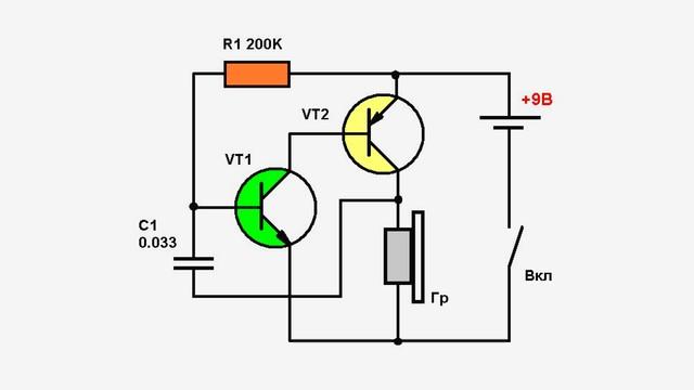
Simple DIY sound generator
Let's consider simplest example- howler You only need four elements: a film capacitor, 2 bipolar transistors and a resistor for adjustment. The load will be an electromagnetic emitter. A simple 9V battery is enough to power the device. The operation of the circuit is simple: the resistor sets the bias to the base of the transistor. Feedback occurs through the capacitor. The tuning resistor changes the frequency. The load must have high resistance.
With all the variety of types, sizes and designs of the considered elements, powerful transistors for ultra-high frequencies have not yet been invented. Therefore, generators based on self-oscillation transistors are used mainly for the low and high frequency ranges.
Video
A high-frequency signal generator is necessary for repairing and tuning radio receivers and is therefore quite in demand. The laboratory generators available on the market are still Soviet-made and have good characteristics, as a rule, are redundant for amateur purposes, but they are quite expensive and often require repairs before use. Simple generators from foreign manufacturers are even more expensive and do not have high parameters. This forces radio amateurs to make such devices themselves.
The generator is designed as an alternative to simple industrial devices similar to the GRG-450B. It operates in all broadcast bands; its production does not require winding inductors and labor-intensive setup. The device implements extended HF ranges, which made it possible to abandon a complex mechanical vernier, a built-in millivoltmeter of the output signal, and frequency modulation. The device is made from cheap, common parts that can be found in any radio amateur who repairs radios.
An analysis of many amateur designs of such generators has revealed a number of common disadvantages characteristic of them: limited frequency range (most cover only the LW, MW and HF bands); Significant frequency overlap in high-frequency ranges makes it difficult to accurately set it and leads to the need to manufacture a vernier. Often it is necessary to wind inductors with taps. In addition, the descriptions of these structures are too brief, and often absent altogether.
It was decided to independently design a high-frequency signal generator that satisfies the following requirements: an extremely simple circuit and design, inductors without taps, the absence of independently manufactured mechanical components, operation in all broadcast bands, including VHF, extended bands and electric vernier. A 50 ohm coaxial output is desirable.
Table
| Range | Frequency, MHz | Voltage 1), mV |
| 94...108 2) |
1) At the coaxial output with a load resistance of 50 Ohms, the effective value.
2) With the variable capacitor disconnected and the voltage across the varicap 0...5 V.
As a result of checking the set technical solutions and repeated modifications, the device described below appeared. The frequency ranges it generates are shown in the table. The accuracy of setting the generator frequency is no worse than ±2 kHz at a frequency of 10 MHz and ±10 kHz at a frequency of 100 MHz. Its shift per hour of operation (after an hour's warm-up) does not exceed 0.2 kHz at a frequency of 10 MHz and 10 kHz at a frequency of 100 MHz. The same table shows the maximum effective output voltage values in each range. The nonlinearity of the millivoltmeter scale is no more than 20%. Supply voltage - 7.5...15 V. The signal generator circuit is shown in Fig. 1.
Rice. 1. Signal generator circuit
As a rule, generators with a point-to-point connection of an oscillating circuit, capable of operating at frequencies above 100 MHz, generate a distorted square wave rather than a sine wave in the mid-wave range. To reduce distortion, a significant change in the operating modes of the active elements of the generator is required depending on the frequency. The signal of the master oscillator used in the described device with connected in series DC field-effect and bipolar transistors have much less distortion. They can be reduced by adjusting the operating mode of only the bipolar transistor.
In low-frequency ranges, the operating mode of transistor VT2 is set by resistors R1 and R9 connected in series. With the transition to high frequency ranges switch SA1.2 closes resistor R1. To increase the steepness of the characteristic of field-effect transistor VT1, a constant bias equal to half the supply voltage is applied to its gate. The supply voltage of the master oscillator is stabilized by the integrated stabilizer DA1. Resistor R10 serves as the minimum load of the stabilizer, without which its output voltage is clogged with noise.
Chokes are used as inductors L1-L10 of the master oscillator industrial production. They are switched by switch SA1.1. In the VHF2 range, inductance L11 is a piece of wire about 75 mm long connecting the switch to printed circuit board.
The deviation of the actual inductance of the inductor from the nominal one can be quite significant, so the range boundaries are selected with some overlap to eliminate their time-consuming installation. The range limits indicated in the table were obtained without any selection of chokes. It is preferable to use chokes big size, the stability of the inductance (and therefore the generated frequency) is higher than that of small-sized ones.
To adjust the frequency, the device uses a three-section variable capacitor with a gearbox, which was used in Ocean radios, Melodiya radios and many others. To ensure that its body does not have electrical contact with the body of the device, it is secured inside it through an insulating gasket. This made it possible to connect one section of the capacitor in series with two others connected in parallel. This is how extended HF bands are implemented. In the ranges DV, SV1 and SV2, where large frequency overlap is required, switch SA1.2 connects the housing variable capacitor with a common wire. In the ranges KV6, VHF1 and VHF2, it is possible to turn off the variable capacitor with switch SA2. When the switch is closed, the stable generation frequency does not exceed 37 MHz.
A circuit consisting of a varicap matrix VD1, capacitors C6, C9 and resistor R6 is connected in parallel to the variable capacitor, serving as a frequency modulator, an electric vernier, and when the variable capacitor is turned off, the main tuning element. Since the amplitude of the high-frequency voltage on the oscillatory circuit reaches several volts, counter-series-connected varicaps of the matrix introduce much less distortion than a single varicap would introduce. The tuning voltage for the varicaps of the matrix VD1 comes from the variable resistor R5. Resistor R2 somewhat linearizes the tuning scale.
The master oscillator is connected to the output follower on transistor VT4 through capacitor C12, the extremely small capacitance of which reduces the influence of the load on the generated frequency and a decrease in the amplitude of the output voltage at frequencies above 30 MHz. To partially eliminate the decrease in amplitude at low frequencies, capacitor C12 is bypassed by circuit R11C14. A simple emitter follower with a high output impedance on a bipolar transistor turned out to be the most suitable solution for such a broadband device. The influence of the load on the frequency is comparable to a source follower on a field-effect transistor, and the dependence of the amplitude on frequency is much less. The use of additional buffer stages only worsened the isolation. To ensure good isolation in the DV-HF ranges, the VT4 transistor must have high coefficient current transmission, and in VHF bands- extremely small interelectrode capacitances.
The repeater output is connected to terminal XT1.4, which is mainly intended for connecting a frequency meter, which leads to a slight decrease in the output voltage. The internal resistance of this output in the HF range is about 120 Ohms, the output voltage is more than 1 V. An indicator of the presence of RF voltage at the repeater output is implemented on diodes VD2, VD3, transistor VT3 and LED HL1.
From the motor of the variable resistor R18, which serves as an output voltage regulator, the signal goes to the divider R19R20, which, in addition to additional decoupling of the generator and the load, provides output impedance coaxial output (XW1 connector) on the HF ranges, close to 50 Ohms. On VHF it drops to 20 ohms.
The frequency shift when changing the position of the R18 engine from the upper position according to the diagram to the lower one reaches 70...100 kHz at a frequency of 100 MHz without load, and with a connected load of 50 Ohms - no more than 2 kHz (at the same frequency).
To measure the output voltage, a detector is provided at connector XW1, made using resistors R15, R17, diode VD4 and capacitor C17. Together with external digital voltmeter or a multimeter in voltmeter mode connected to pins XT 1.3 (plus) and XT1.1 (minus), it forms a millivoltmeter of the effective value of the generator output voltage. To obtain a more linear scale, the VD4 diode is supplied constant pressure bias 1 V, which is set by multi-turn trimmer resistor R17.
The external voltmeter must have a measurement limit of 2 V. In this case, one will be constantly displayed in the high-order digit of its indicator, and the measured output voltage in millivolts will be displayed in the low-order digits. The minimum measured voltage is about 20 mV. Above 100 mV the readings will be slightly higher. At a voltage of 200 mV, the error reaches 20%.
The generator is powered from a stabilized DC voltage source of 7...15 V or from battery. With an unstabilized power supply, the generated high-frequency signal will inevitably be modulated at a frequency of 100 Hz.
The installation of the generator should be approached very carefully; the stability of its parameters depends on this. Most of the parts are installed on a printed circuit board made of insulating material foil-coated on both sides, shown in Fig. 2.

Rice. 2. Printed circuit board made of insulating material foil-coated on both sides

Rice. 3. Location of parts on the board
The arrangement of parts on the board is shown in Fig. 3. The foil areas of the common wire on both sides of the board are connected to each other by wire jumpers soldered into the holes, which are shown filled in. After installation, the elements of the output repeater are covered on both sides of the board with metal screens, the contours of which are shown in dashed lines. These screens must be securely, soldered around the perimeter, connected to the foil of the common wire. In the screen located on the side of the printed conductors, above contact pad, to which the emitter of transistor VT4 is connected, a hole is made through which a copper pin soldered to this pad passes. Subsequently, the central core of the coaxial cable is soldered to it, going to the variable resistor R18 and capacitor C18. The cable braid is connected to the repeater screen.
The generator is mainly used fixed resistors and capacitors for surface mounting of standard size 0805. Resistors R19 and R20 - MLT-0.125. Capacitor C3 is oxide with low ESR, C7 is oxide tantalum K53-19 or similar. Inductors L1-L10 are standard chokes, preferably domestic series DPM, DP2. Compared to imported ones, they have a significantly smaller deviation of inductance from the nominal value and a higher quality factor.
If you do not have a choke of the required rating, you can make the L10 coil yourself by winding eight turns of wire with a diameter of 0.08 mm around an MLT-0.125 resistor with a resistance of at least 1 MOhm. A section of a rigid central wire from a coaxial cable about 75 mm long was used as inductance L11.
Three-section variable capacitors with a gearbox are extremely common, but if one is not available, a two-section one can be used. In this case, the capacitor body is connected to the device body, and each section is connected through a separate switch, and one of the sections is connected through a stretch capacitor. It is much more difficult to control a device with such a variable capacitor.
Switch SA1 - PM 11P2N; similar switches of the PG3 or P2G3 series are also applicable. Switch SA2 - MT1. Variable resistor R18 - SP3-9b, and replace it variable resistor any other type is not recommended. If a variable resistor with the nominal value indicated on the diagram is not found, then you can replace it with a lower nominal value, but at the same time you need to increase the resistance of resistor R16 so that total resistance parallel connected resistors R16 and R18 remained unchanged. Variable resistor R5 - any type, R17 - imported multi-turn trimmer 3296.
Diodes GD407A can be replaced with D311, D18, and diode 1 N4007 can be replaced with any rectifier. Instead of the KVS111A varicap matrix, it is allowed to use KVS111B, and instead of 3AR4UC10 - any red LED.
The master oscillator is insensitive to the types of transistors used. Field effect transistor KP303I can be replaced with KP303G-KP303Zh, KP307A-KP307Zh, and with adjustment printed circuit board- on BF410B-BF410D, KP305Zh. For transistors with an initial current of more than 7 mA, resistor R7 is not required. Bipolar transistor KT3126A can be replaced with any microwave transistor p-n-p structures with minimal interelectrode capacitances. As a replacement for the KT368AM transistor, we can recommend the SS9018I.
The XW1 connector is type F. Any cable can be easily inserted into it, and if necessary, you can simply insert a wire. Clamping block XT1 - WP4-7 for connection speaker systems. Connectors XS1 and XS2 are standard mono jacks for a plug with a diameter of 3.5 mm.
The generator is assembled in a housing from computer unit nutrition. Its installation is shown in the photograph Fig. 4. Remove the fan grille, and cover the side of the case where it was located with a sheet steel plate with holes for connectors and controls. To attach the plate, use all screw holes available in the housing.

Rice. 4. Generator installation
Mount the board on a brass stand 30 mm high, next to the SA1 switch, with the printed conductors facing up. Tin the contact point between the stand and the body and place a contact petal under it, which is connected to the screen of the output repeater. Where possible, avoid the formation of large closed flow loops high frequency current on a common wire, leading to a decrease in the output voltage on the VHF bands.
Place the variable resistor R18 in an additional metal screen, clamping it under the resistor flange. Mounting of resistors R19 and R20 is mounted. Connect their common point to connector XW1 with a coaxial cable. Install the millivoltmeter detector elements on a small circuit board, which is secured directly to the XW1 connector.
Install variable capacitor C4 in the housing through insulating gaskets. It is advisable to make a dielectric extension of the capacitor axis, on which the adjustment knob will be placed. But this is not necessary; it is also permissible to put it on the axis of the capacitor itself. Connect the variable capacitor to the SA2 switch and to the board using a rigid central core from the coaxial cable. Install capacitor C5 and connect it to the housing next to capacitor C4.
Before installing the switch SA1 into the device, mount inductors L1-L10 and resistor R1 on it. The axes of adjacent coils must be mutually perpendicular, otherwise their mutual influence cannot be avoided. This is especially true for low-frequency ranges. It is convenient to alternate coils with axial and radial leads. Connect the common wire to galette SA1.1 with a harness of ten or more MGTF wires. Using a separate wire, connect the resistor R1 and the moving contact of the biscuit SA1.2 to the common wire.
Using a syringe with a shortened needle, apply all the necessary inscriptions to the front panel with tinted tsapon varnish. Input connector sawtooth voltage Mount XS2 on the rear panel to prevent accidental connection to it. Lead the power cord there as well. It is duplicated by contacts XT1.1 (minus) and XT1.2 (plus), from which you can power other measuring instruments or custom device. Cover all excess holes in the case with steel plates soldered to it.
Once assembled according to the recommendations, the device should work immediately. The DC voltage at the emitter of transistor VT4 should be measured. When the motor of the variable resistor R18 is in the upper (according to the diagram) position, it should not be less than 2 V, otherwise you need to reduce the resistance of the resistor R13. Next, you need to check the operation of the generator on all ranges. On VHF, with a large introduced capacitance of the variable capacitor (if it is turned on), the oscillations fail, which is evident from the decrease in the brightness of the HL1 LED.
If the variable resistor R5 is turned on, as shown in the diagram, then the tuning bandwidth on the VHF bands will not exceed 15 MHz, and these ranges may need to be within the broadcast range. First of all, do this in the VHF1 band (65.9...74 MHz) using trimmer capacitor C9 with switch SA2 open. Next, move the switch SA1 to the VHF2 position and, by changing the length of the piece of wire that serves as inductance L11, achieve overlap of the broadcast range 87.5...108 MHz. If you need to greatly increase the frequency, a piece of wire can be replaced with a strip of copper foil or flattened braid of a coaxial cable. The frequency tuning limits of a varicap can be significantly increased if the variable resistor R5 is supplied with voltage from the input, and not from the output, of the integrated stabilizer DA1. But this will lead to a noticeable deterioration in frequency stability.
Adjusting the millivoltmeter detector consists of setting the trimmer resistor R17 to a voltage of 1010 mV on the multimeter connected to the output of the detector at zero output voltage of the generator (the slider of the variable resistor R18 is in the lower position in the diagram). Next, using a variable resistor to increase the output voltage swing to 280 mV (monitored with an oscilloscope), adjust R17 so that the multimeter shows 1100 mV. It corresponds effective value output voltage 100 mV. It should be taken into account that RF voltage less than 20 mV cannot be measured with this millivoltmeter (dead zone), and at a voltage of more than 100 mV its readings will be greatly overestimated.
PCB file in format Sprint Layout 6.0 can be downloaded.
Literature
1. High-frequency signal generator GRG-450B. - URL: http://www.printsip.ru/cgi/download/instr/GW_instek/generatori_ gw/grg-450b.pdf (09.26.15).
2. Shortwave GIR (Abroad). - Radio, 2006, No. 11, p. 72, 73.
Publication date: 12.01.2016
Readers' opinions
- alex286 / 10/17/2018 - 20:03
In the ranges KV6, VHF1 and VHF2, it is possible to turn off the variable capacitor with switch SA2. When the switch is closed, the stable generation frequency does not exceed 37 MHz. - alex286 / 10.15.2018 - 14:46
Did you get banned from Google or something? It’s one, two.. Lie like children, give them everything, give it, and bring it.. - Sasha / 05/08/2018 - 14:23
I can't start the generator below 60 MHz - Kirill / 08/10/2017 - 19:22
Why is it not written what R5 SA2 C6 is for??? Where is the link to the original source? Perhaps there is a more complete description there?