Bipolar transistor what is the saturation voltage datasheet. Bipolar transistor - detailed description of all semiconductor parameters
So, the third and final part of the story about bipolar transistors on our website =) Today we will talk about the use of these wonderful devices as amplifiers, we will consider possible bipolar transistor switching circuits and their main advantages and disadvantages. Let's get started!
This circuit is very good when using high frequency signals. In principle, this is why the transistor is turned on in the first place. Very big disadvantages are the low input resistance and, of course, the lack of current amplification. See for yourself, at the input we have the emitter current, at the output.
That is, the emitter current is greater than the collector current by a small amount of the base current. This means that there is not just no current gain, moreover, the output current is slightly less than the input current. Although, on the other hand, this circuit has a fairly large voltage transfer coefficient) These are the advantages and disadvantages, let’s continue….
Connection diagram for a bipolar transistor with a common collector

This is what the wiring diagram for a bipolar transistor looks like: common collector. Does it remind you of anything?) If we look at the circuit from a slightly different angle, we recognize our old friend here - the emitter follower. There was almost a whole article about it (), so we have already covered everything related to this scheme. Meanwhile, we are waiting for the most commonly used circuit - with a common emitter.
Connection circuit for a bipolar transistor with a common emitter.

This circuit has earned popularity for its amplifying properties. Of all the circuits, it gives the greatest gain in current and voltage; accordingly, the increase in signal power is also large. The disadvantage of the circuit is that the amplification properties are strongly influenced by increasing temperature and signal frequency.
We got acquainted with all the circuits, now let’s take a closer look at the last (but not the least important) amplifier circuit based on a bipolar transistor (with a common emitter). First, let's depict it a little differently:

There is one minus here - the grounded emitter. When the transistor is turned on in this way, the output contains nonlinear distortion, which, of course, need to be fought. Nonlinearity occurs due to the influence of the input voltage on the emitter-base junction voltage. Indeed, there is nothing “extra” in the emitter circuit; the entire input voltage turns out to be applied precisely to the base-emitter junction. To cope with this phenomenon, we add a resistor to the emitter circuit. So we get negative feedback.
What is this?
To put it briefly, then negative inverse principle th communications lies in the fact that some part of the output voltage is transferred to the input and subtracted from the input signal. Naturally, this leads to a decrease in the gain, since the input of the transistor, due to the influence of feedback, will receive a lower voltage value than in the absence of feedback.
Nevertheless, negative feedback is very useful for us. Let's see how it will help reduce the influence of the input voltage on the voltage between the base and emitter.
So, even if there is no feedback, an increase in the input signal by 0.5 V leads to the same increase. Everything is clear here 😉 And now let’s add feedback! And in the same way, we increase the input voltage by 0.5 V. Following this, , increases, which leads to an increase in the emitter current. And an increase leads to an increase in the voltage across the feedback resistor. It would seem, what's wrong with this? But this voltage is subtracted from the input! Look what happened:
The input voltage has increased - the emitter current has increased - the voltage across the negative feedback resistor has increased - the input voltage has decreased (due to subtraction) - the voltage has decreased.
That is, negative feedback prevents the base-emitter voltage from changing when the input signal changes.
As a result, our amplifier circuit with a common emitter was supplemented with a resistor in the emitter circuit:

There is another problem with our amplifier. If a negative voltage value appears at the input, the transistor will immediately close (the base voltage will become less than the emitter voltage and the base-emitter diode will close), and nothing will happen at the output. This is somehow not very good) Therefore, it is necessary to create bias. This can be done using a divisor as follows:

We got such a beauty 😉 If the resistors are equal, then the voltage on each of them will be equal to 6V (12V / 2). Thus, in the absence of a signal at the input, the base potential will be +6V. If a negative value comes to the input, for example, -4V, then the base potential will be equal to +2V, that is, the value is positive and not interfering normal operation transistor. This is how useful it is to create an offset in the base circuit)
How else could we improve our scheme...
Let us know what signal we will amplify, that is, we know its parameters, in particular the frequency. It would be great if there was nothing at the input except the useful amplified signal. How to ensure this? Of course, using a high-pass filter) Let's add a capacitor, which, in combination with a bias resistor, forms a high-pass filter:

This is how the circuit, in which there was almost nothing except the transistor itself, was overgrown with additional elements 😉 Perhaps we’ll stop there; soon there will be an article devoted to the practical calculation of an amplifier based on a bipolar transistor. In it we will not only compose schematic diagram amplifier, but we will also calculate the values of all elements, and at the same time select a transistor suitable for our purposes. See you soon! =)
Bipolar transistor.
Bipolar transistor- an electronic semiconductor device, a type of transistor, designed to amplify, generate and convert electrical signals. The transistor is called bipolar, since two types of charge carriers simultaneously participate in the operation of the device - electrons And holes. This is how it differs from unipolar(field-effect) transistor, in which only one type of charge carrier is involved.
The principle of operation of both types of transistors is similar to the operation of a water tap that regulates the flow of water, only a flow of electrons passes through the transistor. In bipolar transistors, two currents pass through the device - the main “large” current, and the control “small” current. The main current power depends on the control power. For field-effect transistors, only one current passes through the device, the power of which depends on electromagnetic field. In this article we will take a closer look at the operation of a bipolar transistor.
Bipolar transistor design.
A bipolar transistor consists of three semiconductor layers and two PN junctions. PNP and NPN transistors are distinguished according to the type of alternation hole and electron conductivities. It's like two diode, connected face to face or vice versa.

A bipolar transistor has three contacts (electrodes). The contact coming out of the central layer is called base. The extreme electrodes are called collector And emitter (collector And emitter). The base layer is very thin relative to the collector and emitter. In addition to this, the semiconductor regions at the edges of the transistor are asymmetrical. The semiconductor layer on the collector side is slightly thicker than on the emitter side. This is necessary for the transistor to operate correctly.

Operation of a bipolar transistor.
Let's consider the physical processes occurring during operation of a bipolar transistor. Let's take the NPN model as an example. Operating principle PNP transistor is similar, only the polarity of the voltage between the collector and emitter will be opposite.
As already stated in article on types of conductivity in semiconductors, in a P-type substance there are positively charged ions - holes. N-type substance is saturated with negatively charged electrons. In a transistor, the concentration of electrons in the N region significantly exceeds the concentration of holes in the P region.
Let's connect a voltage source between the collector and emitter V CE (V CE). Under its action, electrons from the upper N part will begin to be attracted to the plus and collect near the collector. However, current will not be able to flow because the electric field of the voltage source does not reach the emitter. This is prevented by a thick layer of collector semiconductor plus a layer of base semiconductor.

Now let's connect the voltage between base and emitter V BE , but significantly lower than V CE (for silicon transistors the minimum required V BE is 0.6V). Since the layer P is very thin, plus a voltage source connected to the base, it will be able to “reach” with its electric field the N region of the emitter. Under its influence, electrons will be directed to the base. Some of them will begin to fill the holes located there (recombine). The other part will not find a free hole, because the concentration of holes in the base is much lower than the concentration of electrons in the emitter.
As a result, the central layer of the base is enriched with free electrons. Most of them will go towards the collector, since the voltage is much higher there. This is also facilitated by the very small thickness of the central layer. Some part of the electrons, although much smaller, will still flow towards the plus side of the base.

As a result, we get two currents: a small one - from the base to the emitter I BE, and a large one - from the collector to the emitter I CE.
If you increase the voltage at the base, then even more electrons will accumulate in the P layer. As a result, the base current will increase slightly and the collector current will increase significantly. Thus, with a slight change in base current I B , the collector current I changes greatly WITH. That's what happens signal amplification in a bipolar transistor. The ratio of the collector current I C to the base current I B is called the current gain. Designated β , hfe or h21e, depending on the specifics of the calculations carried out with the transistor.
The simplest bipolar transistor amplifier
Let us consider in more detail the principle of signal amplification in the electrical plane using the example of a circuit. Let me make a reservation in advance that this scheme is not entirely correct. No one connects a DC voltage source directly to an AC source. But in in this case, this will be easier and more clear for understanding the amplification mechanism itself using a bipolar transistor. Also, the calculation technique itself in the example below is somewhat simplified.
1.Description of the main elements of the circuit
So, let’s say we have a transistor with a gain of 200 (β = 200). On the collector side, we will connect a relatively powerful 20V power source, due to the energy of which amplification will occur. From the base of the transistor we connect a weak 2V power source. We connect the source to it in series AC voltage in the form of a sine, with an oscillation amplitude of 0.1V. This will be a signal that needs to be amplified. The resistor Rb near the base is necessary in order to limit the current coming from the signal source, which usually has low power.

2. Calculation of base input current I b
Now let's calculate the base current I b. Since we are dealing with alternating voltage, we need to calculate two current values - at the maximum voltage (V max) and the minimum (V min). Let's call these current values respectively - I bmax and I bmin.
Also, in order to calculate the base current, you need to know the base-emitter voltage V BE. There is one PN junction between the base and emitter. It turns out that the base current “meets” the semiconductor diode on its path. The voltage at which a semiconductor diode begins to conduct is about 0.6V. Let's not go into details current-voltage characteristics of the diode, and for simplicity of calculations, we take an approximate model, according to which the voltage on the current-carrying diode is always 0.6V. This means that the voltage between the base and emitter is V BE = 0.6V. And since the emitter is connected to ground (V E = 0), the voltage from base to ground is also 0.6V (V B = 0.6V).
Let's calculate I bmax and I bmin using Ohm's law:

2. Calculation of output collector current I WITH
Now, knowing the gain (β = 200), you can easily calculate the maximum and minimum values of the collector current (I cmax and I cmin).

3. Calculation of output voltage V out
The collector current flows through the resistor Rc, which we have already calculated. It remains to substitute the values:
4. Analysis of results
As can be seen from the results, V Cmax turned out to be less than V Cmin. This is because the voltage across the resistor V Rc is subtracted from the supply voltage VCC. However, in most cases this does not matter, since we are interested in the variable component of the signal - the amplitude, which has increased from 0.1V to 1V. The frequency and sinusoidal shape of the signal have not changed. Of course, the V out / V in ratio of ten times is far from the best indicator for an amplifier, but it is quite suitable for illustrating the amplification process.

So, let's summarize the principle of operation of an amplifier based on a bipolar transistor. A current I b flows through the base, carrying constant and variable components. A constant component is needed so that the PN junction between the base and emitter begins to conduct - “opens”. The variable component is, in fact, the signal itself (useful information). The collector-emitter current inside the transistor is the result of the base current multiplied by the gain β. In turn, the voltage across the resistor Rc above the collector is the result of multiplying the amplified collector current by the resistor value.
Thus, the V out pin receives a signal with an increased oscillation amplitude, but with the same shape and frequency. It is important to emphasize that the transistor takes energy for amplification from the VCC power source. If the supply voltage is insufficient, the transistor will not be able to operate fully, and the output signal may be distorted.
Operating modes of a bipolar transistor
In accordance with the voltage levels on the electrodes of the transistor, there are four modes of its operation:
Cut off mode.
Active mode.
Saturation mode.
Reverse mode.
Cut-off mode
When the base-emitter voltage is lower than 0.6V - 0.7V, the PN junction between the base and emitter is closed. In this state, the transistor has no base current. As a result, there will be no collector current either, since there are no free electrons in the base ready to move towards the collector voltage. It turns out that the transistor is, as it were, locked, and they say that it is in cut-off mode.
Active mode
IN active mode The voltage at the base is sufficient for the PN junction between the base and the emitter to open. In this state, the transistor has base and collector currents. The collector current equals the base current multiplied by the gain. That is, the active mode is the normal operating mode of the transistor, which is used for amplification.
Saturation mode
Sometimes the base current may be too high. As a result, the supply power is simply not enough to provide such a magnitude of collector current that would correspond to the gain of the transistor. In saturation mode, the collector current will be the maximum that the power supply can provide and will not depend on the base current. In this state, the transistor is not able to amplify the signal, since the collector current does not respond to changes in the base current.
In saturation mode, the conductivity of the transistor is maximum and it is more suitable for the function of a switch (switch) in the “on” state. Similarly, in the cut-off mode, the conductivity of the transistor is minimal, and this corresponds to the switch in the off state.
Inverse mode
In this mode, the collector and emitter change roles: the collector PN junction is biased in the forward direction, and the emitter junction is biased in the opposite direction. As a result, current flows from the base to the collector. The collector semiconductor region is asymmetrical to the emitter, and the gain in inverse mode is lower than in normal active mode. The transistor is designed in such a way that it operates as efficiently as possible in active mode. Therefore, the transistor is practically not used in inverse mode.
Basic parameters of a bipolar transistor.
Current gain– ratio of collector current I C to base current I B. Designated β , hfe or h21e, depending on the specifics of the calculations carried out with transistors.
β is a constant value for one transistor, and depends on the physical structure of the device. A high gain is calculated in hundreds of units, a low gain - in tens. For two separate transistors of the same type, even if they were “pipeline neighbors” during production, β may be slightly different. This characteristic of a bipolar transistor is perhaps the most important. If other parameters of the device can often be neglected in calculations, then the current gain is almost impossible.
Input impedance– resistance in the transistor that “meets” the base current. Designated R in (R input). The larger it is, the better for the amplification characteristics of the device, since the source is usually located on the base side weak signal, which needs to consume as little current as possible. The ideal option is when the input impedance is infinity.
R input for an average bipolar transistor is several hundred KΩ (kilo-ohms). Here the bipolar transistor loses very much to the field-effect transistor, where the input resistance reaches hundreds of GΩ (gigaohms).
Output conductivity- conductivity of the transistor between collector and emitter. The greater the output conductance, the more collector-emitter current will be able to pass through the transistor at less power.
Also, with an increase in output conductivity (or a decrease in output resistance), the maximum load that the amplifier can withstand with insignificant losses in overall gain increases. For example, if a transistor with low output conductivity amplifies the signal 100 times without a load, then when a 1 KΩ load is connected, it will already amplify only 50 times. A transistor with the same gain but higher output conductance will have a smaller gain drop. The ideal option is when the output conductivity is infinity (or output resistance R out = 0 (R out = 0)).
The transistor is ubiquitous and important component in modern microelectronics. Its purpose is simple: it allows you to control a much stronger one using a weak signal.
In particular, it can be used as a controlled “damper”: by the absence of a signal at the “gate”, block the flow of current, and by supplying it, allow it. In other words: this is a button that is pressed not by a finger, but by applying voltage. IN digital electronics this is the most common application.
Transistors are available in different packages: the same transistor can look completely different in appearance. In prototyping, the most common cases are:
TO-92 - compact, for light loads
TO-220AB - massive, good heat dissipation, for heavy loads
The designation on the diagrams also varies depending on the type of transistor and the designation standard used in the compilation. But regardless of the variation, its symbol remains recognizable.
Bipolar transistors
Bipolar junction transistors (BJT, Bipolar Junction Transistors) have three contacts:
Collector - it is fed high voltage that you want to manage
Base - a small amount is supplied through it current to unlock large; the base is grounded to block it
Emitter - current flows through it from the collector and base when the transistor is “open”
![]()
The main characteristic of a bipolar transistor is the indicator hfe also known as gain. It reflects how many times more current in the collector-emitter section the transistor can pass in relation to the base-emitter current.
For example, if hfe= 100, and 0.1 mA passes through the base, then the transistor will pass through itself a maximum of 10 mA. If in this case there is a component in the high current section that consumes, for example, 8 mA, it will be provided with 8 mA, and the transistor will have a “reserve”. If there is a component that draws 20 mA, it will only be provided with the maximum 10 mA.
Also in the documentation for each transistor the maximum permissible stresses and currents on the contacts. Exceeding these values leads to excessive heating and reduced service life, and a strong excess can lead to destruction.
NPN and PNP
![]()
The transistor described above is a so-called NPN transistor. It is called that because it consists of three layers of silicon connected in the order: Negative-Positive-Negative. Where negative is a silicon alloy with an excess of negative charge carriers (n-doped), and positive is an alloy with an excess of positive charge carriers (p-doped).
NPNs are more effective and common in industry.
When designating PNP transistors, they differ in the direction of the arrow. The arrow always points from P to N. PNP transistors have an “inverted” behavior: current is not blocked when the base is grounded and blocked when current flows through it.
Field effect transistors
Field effect transistors (FET, Field Effect Transistor) have the same purpose, but differ in internal structure. A particular type of these components are MOSFET transistors(Metal-Oxide-Semiconductor Field Effect Transistor). They allow you to operate much more high power with the same dimensions. And the control of the “damper” itself is carried out exclusively using voltage: no current flows through the gate, unlike bipolar transistors.
Field effect transistors have three contacts:
Drain - high voltage is applied to it, which you want to control
Gate - voltage is applied to it to allow current to flow; the gate is grounded to block the current.
Source - current flows through it from the drain when the transistor is “open”
![]()
N-Channel and P-Channel
![]()
By analogy with bipolar transistors, field transistors differ in polarity. The N-Channel transistor was described above. They are the most common.
P-Channel when designated differs in the direction of the arrow and, again, has an “inverted” behavior.
Connecting transistors to drive high-power components
A typical task of a microcontroller is to turn a specific circuit component on and off. The microcontroller itself usually has modest power handling characteristics. So Arduino, with 5 V output per pin, can withstand a current of 40 mA. Powerful motors or ultra-bright LEDs can draw hundreds of milliamps. When connecting such loads directly, the chip can quickly fail. In addition, for the operation of some components, a voltage greater than 5 V is required, and Arduino cannot produce more than 5 V from the digital output pin.
But it is easily enough to control a transistor, which in turn will control a large current. Let's say we need to connect a long LED strip, which requires 12 V and still consumes 100 mA:
![]()
Now, when the output is set to logical one (high), the 5 V entering the base will open the transistor and current will flow through the tape - it will glow. When the output is set to logic zero (low), the base will be grounded through the microcontroller and current flow will be blocked.
Pay attention to the current limiting resistor R. It is necessary to prevent the formation of short circuit along the route microcontroller - transistor - ground. The main thing is not to exceed the permissible current through the Arduino contact of 40 mA, so you need to use a resistor with a value of at least:
Here Ud- this is the voltage drop across the transistor itself. It depends on the material from which it is made and is usually 0.3 – 0.6 V.
But it is absolutely not necessary to keep the current at the permissible limit. It is only necessary that the gain of the transistor allows you to control the required current. In our case it is 100 mA. Acceptable for the transistor used hfe= 100, then a control current of 1 mA will be enough for us
A resistor with a value from 118 Ohm to 4.7 kOhm is suitable for us. For stable operation on one side and light load on the chip on the other, 2.2 kOhm is a good choice.
If you use a field-effect transistor instead of a bipolar transistor, you can do without a resistor:
![]()
This is due to the fact that the gate in such transistors is controlled solely by voltage: there is no current in the microcontroller - gate - source section. And thanks to their high performance circuit using MOSFET, allows you to drive very powerful components.
A transistor is a semiconductor device that can amplify, convert and generate electrical signals. The first functional bipolar transistor was invented in 1947. The material for its manufacture was germanium. And already in 1956, the silicon transistor was born.
A bipolar transistor uses two types of charge carriers - electrons and holes, which is why such transistors are called bipolar. In addition to bipolar ones, there are unipolar (field-effect) transistors, which use only one type of carrier - electrons or holes. This article will discuss.
Most silicon transistors have an n-p-n structure, which is also explained by manufacturing technology, although silicon transistors also exist p-n-p type, but there are slightly fewer of them than n-p-n structures. Such transistors are used as part of complementary pairs (transistors different conductivity with the same electrical parameters). For example, KT315 and KT361, KT815 and KT814, and in the output stages of transistor UMZCH KT819 and KT818. Imported amplifiers often use the powerful complementary pair 2SA1943 and 2SC5200.
Transistors of p-n-p structure are often called direct conduction transistors, and structures n-p-n reverse. For some reason, this name almost never appears in the literature, but among radio engineers and radio amateurs it is used everywhere, everyone immediately understands what we are talking about. Figure 1 shows a schematic design of transistors and their graphic symbols.

Figure 1.
In addition to differences in type of conductivity and material, bipolar transistors are classified by power and operating frequency. If the power dissipation on a transistor does not exceed 0.3 W, such a transistor is considered low-power. With a power of 0.3...3 W, the transistor is called a medium-power transistor, and with a power of over 3 W, the power is considered high. Modern transistors are able to dissipate power of several tens and even hundreds of watts.
Transistors do not amplify electrical signals equally well: as the frequency increases, the gain of the transistor cascade decreases, and at a certain frequency it stops altogether. Therefore, to work in wide range frequency transistors are available with different frequency properties.
Based on the operating frequency, transistors are divided into low-frequency - operating frequency not exceeding 3 MHz, mid-frequency - 3...30 MHz, high-frequency - over 30 MHz. If the operating frequency exceeds 300 MHz, then these are already ultra-high-frequency transistors.
In general, serious thick reference books list over 100 different parameters of transistors, which also indicates a huge number of models. And the number of modern transistors is such that it is no longer possible to place them in full in any reference book. AND model range is constantly increasing, allowing us to solve almost all problems set by the developers.
There are many transistor circuits(just remember the number of household equipment) for amplifying and converting electrical signals, but, despite all the diversity, these circuits consist of separate cascades, the basis of which are transistors. To achieve the required signal amplification, it is necessary to use several amplification stages connected in series. To understand how amplifier stages work, you need to become more familiar with the transistor connection circuits.
The transistor itself cannot amplify anything. Its amplifying properties lie in the fact that small changes in the input signal (current or voltage) lead to significant changes in voltage or current at the output of the stage due to the expenditure of energy from external source. It is this property that is widely used in analog circuits, - amplifiers, television, radio, communications, etc.
To simplify the presentation, circuits based on n-p-n transistors will be considered here. Everything that will be said about these transistors applies equally to pnp transistors. It is enough just to change the polarity of the power supplies, and, if any, to get a working circuit.
In total, three such circuits are used: a circuit with a common emitter (CE), a circuit with a common collector (OC) and a circuit with a common base (CB). All these schemes are shown in Figure 2.

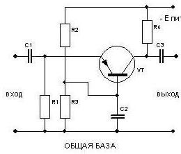
Figure 2.
But before moving on to considering these circuits, you should get acquainted with how a transistor works in switching mode. This introduction should make it easier to understand in boost mode. In a certain sense, the key circuit can be considered as a type of circuit with OE.
Transistor operation in switching mode
Before studying the operation of a transistor in signal amplification mode, it is worth remembering that transistors are often used in switching mode.
This mode of operation of the transistor has been considered for a long time. The August 1959 issue of Radio magazine published an article by G. Lavrov, “Semiconductor triode in switch mode.” The author of the article proposed changing the duration of the pulses in the control winding (OC). Now this control method is called PWM and is used quite often. A diagram from a magazine of the time is shown in Figure 3.

Figure 3.
But key mode is used not only in PWM systems. Often a transistor simply turns something on and off.
In this case, a relay can be used as a load: if an input signal is given, the relay is turned on; if not, the relay signal is turned off. Instead of relays, light bulbs are often used in key mode. This is usually done to indicate: the light is either on or off. The diagram of such a key stage is shown in Figure 4. Key stages are also used to work with LEDs or optocouplers.
Figure 4.
In the figure, the cascade is controlled by a regular contact, although there may be a digital chip or instead. A car light bulb, this one is used to illuminate the dashboard in Zhiguli cars. You should pay attention to the fact that the control voltage is 5V, and the switched collector voltage is 12V.
There is nothing strange about this, since voltages do not play any role in this circuit, only currents matter. Therefore, the light bulb can be at least 220V, if the transistor is designed to operate at such voltages. The collector source voltage must also match the operating voltage of the load. Using such cascades, the load is connected to digital chips or microcontrollers.
In this circuit, the base current controls the collector current, which, due to the energy of the power source, is several tens or even hundreds of times greater (depending on the collector load) than the base current. It is easy to see that current amplification occurs. When a transistor operates in switching mode, the cascade is usually calculated using a value called in reference books “current gain in large signal mode” - in reference books it is denoted by the letter β. This is the ratio of the collector current, determined by the load, to the minimum possible base current. In the form mathematical formula it looks like this: β = Ik/Ib.
For most modern transistors, the β coefficient is quite large, as a rule, from 50 and higher, so when calculating the key stage it can be taken equal to only 10. Even if the base current turns out to be greater than the calculated one, then the transistor will not open stronger because of this, so it and key mode.
To light the light bulb shown in Figure 3, Ib = Ik/β = 100mA/10 = 10mA, this is the minimum. With a control voltage of 5V across the base resistor Rb, minus the voltage drop in section B-E, there will remain 5V - 0.6V = 4.4V. The resistance of the base resistor will be: 4.4V / 10mA = 440 Ohms. From standard range a resistor with a resistance of 430 ohms is selected. A voltage of 0.6V is the voltage at the B-E junction, and you should not forget about it when calculating!
To ensure that the base of the transistor does not remain “hanging in the air” when the control contact opens, the B-E junction is usually shunted by a resistor Rbe, which reliably closes the transistor. This resistor should not be forgotten, although in some circuits for some reason it is not present, which can lead to false operation of the cascade due to interference. Actually, everyone knew about this resistor, but for some reason they forgot, and once again stepped on the “rake”.
The value of this resistor must be such that when the contact opens, the voltage at the base would not be less than 0.6V, otherwise the cascade will be uncontrollable, as if section B-E was simply short-circuited. In practice, resistor Rbe is installed with a nominal value approximately ten times greater than Rb. But even if the Rb rating is 10K, the circuit will work quite reliably: the base and emitter potentials will be equal, which will lead to the transistor closing.
Such a key cascade, if it is working properly, can turn the light bulb on at full intensity, or turn it off completely. In this case, the transistor can be completely open (saturation state) or completely closed (cut-off state). Immediately, the conclusion suggests itself that between these “boundary” states there is such a thing when the light bulb shines at full intensity. In this case, is the transistor half open or half closed? It's like the filling-a-glass problem: an optimist sees the glass as half full, while a pessimist sees it as half empty. This mode of operation of the transistor is called amplification or linear.
Transistor operation in signal amplification mode
Almost all modern electronics consists of microcircuits in which transistors are “hidden”. Simply select the operating mode operational amplifier to obtain the required gain or bandwidth. But, despite this, cascades on discrete (“scattered”) transistors are often used, and therefore an understanding of the operation of the amplifier stage is simply necessary.
The most common connection of a transistor compared to OK and OB is a common emitter (CE) circuit. The reason for this prevalence is primarily high coefficient voltage and current gain. The highest gain of the OE cascade is achieved when half the power supply voltage Epit/2 drops at the collector load. Accordingly, the second half falls on the site K-E transistor. This is achieved by setting up the cascade, which will be discussed below. This amplification mode is called class A.
When the OE transistor is turned on, the output signal at the collector is out of phase with the input. As disadvantages, it can be noted that the input impedance of the OE is small (no more than a few hundred ohms), and the output impedance is within tens of kOhms.
If in the switching mode the transistor is characterized by a current gain in large-signal mode β, then in amplification mode the “current gain in small-signal mode” is used, designated h21e in reference books. This designation comes from the representation of a transistor as a four-terminal network. The letter “e” indicates that the measurements were made when a transistor with a common emitter was turned on.
The coefficient h21e, as a rule, is slightly larger than β, although it can also be used in calculations as a first approximation. All the same, the spread of parameters β and h21e is so large even for one type of transistor that the calculations are only approximate. After such calculations, as a rule, configuration of the circuit is required.
The gain of the transistor depends on the thickness of the base, so it cannot be changed. Hence the large spread in the gain of transistors taken even from the same box (read one batch). For low-power transistors this coefficient ranges from 100...1000, and for high-power ones 5...200. The thinner the base, the higher the coefficient.
The simplest circuit for switching on an OE transistor is shown in Figure 5. This is just a small piece from Figure 2, shown in the second part of the article. This type of circuit is called a fixed base current circuit.

Figure 5.
The scheme is extremely simple. The input signal is fed to the base of the transistor through the coupling capacitor C1, and, being amplified, is removed from the collector of the transistor through capacitor C2. The purpose of capacitors is to protect the input circuits from the constant component of the input signal (just remember a carbon or electret microphone) and provide the necessary cascade bandwidth.
Resistor R2 is the collector load of the cascade, and R1 supplies a constant bias to the base. Using this resistor, they try to make sure that the voltage at the collector is Epit/2. This state is called the operating point of the transistor; in this case, the gain of the cascade is maximum.
Approximately the resistance of resistor R1 can be determined by the simple formula R1 ≈ R2 * h21e / 1.5...1.8. The coefficient 1.5...1.8 is adjusted depending on the supply voltage: at low voltage (no more than 9V) the coefficient value is no more than 1.5, and starting from 50V it approaches 1.8...2.0. But, indeed, the formula is so approximate that resistor R1 most often has to be selected, otherwise the required value of Epit/2 at the collector will not be obtained.
Collector resistor R2 is specified as a condition of the problem, since the collector current and the gain of the cascade as a whole depend on its value: the greater the resistance of resistor R2, the higher the gain. But you need to be careful with this resistor; the collector current should be less than the maximum permissible for of this type transistor.
The circuit is very simple, but this simplicity also gives it negative properties, and you have to pay for this simplicity. Firstly, the gain of the cascade depends on the specific instance of the transistor: if you replaced the transistor during repair, select the bias again, bring it to the operating point.
Secondly, on temperature environment, - with increasing temperature, the reverse collector current Iko increases, which leads to an increase in the collector current. And where then is half the supply voltage at the collector Epit/2, that same operating point? As a result, the transistor heats up even more, after which it fails. To get rid of this addiction, or, according to at least, to reduce it to a minimum, introduce additional elements negative feedback - OOS.
Figure 6 shows a circuit with a fixed bias voltage.

Figure 6.
It would seem that the voltage divider Rb-k, Rb-e will provide the required initial bias of the cascade, but in fact, such a cascade has all the disadvantages of a circuit with a fixed current. Thus, the circuit shown is just a variation of the fixed current circuit shown in Figure 5.
Temperature-stabilized circuits
The situation is somewhat better when using the circuits shown in Figure 7.

Figure 7.
In a collector-stabilized circuit, bias resistor R1 is connected not to the power source, but to the collector of the transistor. In this case, if the reverse current increases as the temperature increases, the transistor opens more strongly, and the voltage on the collector decreases. This reduction results in a decrease in the bias voltage supplied to the base through R1. The transistor begins to close, the collector current decreases to an acceptable value, and the position of the operating point is restored.
It is quite obvious that such a stabilization measure leads to some reduction in the gain of the cascade, but this does not matter. The missing gain is usually added by increasing the number of amplification stages. But such environmental protection allows you to significantly expand the range of operating temperatures of the cascade.
The circuit design of a cascade with emitter stabilization is somewhat more complex. The amplifying properties of such cascades remain unchanged over an even wider temperature range than that of a collector-stabilized circuit. And one more thing undeniable advantage, - when replacing a transistor, you do not have to re-select the operating modes of the cascade.
Emitter resistor R4, while providing temperature stabilization, also reduces the cascade gain. This is for DC. In order to eliminate the influence of resistor R4 on the gain AC, resistor R4 is shunted by capacitor Ce, which for alternating current represents insignificant resistance. Its value is determined by the frequency range of the amplifier. If these frequencies lie in the audio range, then the capacitance of the capacitor can be from units to tens and even hundreds of microfarads. For radio frequencies this is already hundredths or thousandths, but in some cases the circuit works fine without this capacitor.
In order to better understand how emitter stabilization works, we need to consider the connection circuit of a transistor with a common collector OK.
A circuit with a common collector (OC) is shown in Figure 8. This circuit is a piece of Figure 2, from the second part of the article, which shows all three circuits for connecting transistors.

Figure 8.
The load of the cascade is the emitter resistor R2, the input signal is supplied through capacitor C1, and the output signal is removed through capacitor C2. Here you can ask why this scheme is called OK? After all, if you recall the OE circuit, you can clearly see that the emitter is connected to the common wire of the circuit, relative to which the input signal is supplied and the output signal is removed.
In the OK circuit, the collector is simply connected to the power source, and at first glance it seems that it has nothing to do with the input and output signals. But in fact, the EMF source (battery) has a very small internal resistance, for a signal it is practically one point, one and the same contact.
The operation of the OK circuit can be examined in more detail in Figure 9.

Figure 9.
It is known that for silicon transistors the voltage transition b-e is in the range of 0.5...0.7V, so you can take it on average 0.6V, if you do not set out to carry out calculations with an accuracy of tenths of a percent. Therefore, as can be seen in Figure 9, output voltage will always be less than the input value by Ub-e, namely by the same 0.6V. Unlike the OE circuit, this circuit does not invert the input signal, it simply repeats it, and even reduces it by 0.6V. This circuit is also called an emitter follower. Why is such a scheme needed, what is its benefit?
The OK circuit amplifies the current signal by h21e times, which indicates that the input resistance of the circuit is h21e times greater than the resistance in the emitter circuit. In other words, you can, without fear of burning the transistor, supply voltage directly to the base (without a limiting resistor). Just take the base pin and connect it to the +U power bus.
High input impedance allows you to connect a high impedance (impedance) input source, such as a piezoelectric pickup. If such a pickup is connected to a cascade according to the OE circuit, then the low input impedance of this stage will simply “plant” the signal of the pickup - “the radio will not play.”
A distinctive feature of the OK circuit is that its collector current Ik depends only on the load resistance and the voltage of the input signal source. In this case, the transistor parameters do not play any role here at all. Such circuits are said to be covered by 100% voltage feedback.
As shown in Figure 9, the current in the emitter load (aka emitter current) Iн = Iк + Ib. Taking into account that the base current Ib is negligible compared to the collector current Ik, we can assume that the load current is equal to the collector current Il = Ik. The current in the load will be (Uin - Ube)/Rn. In this case, we will assume that Ube is known and is always equal to 0.6V.
It follows that the collector current Ik = (Uin - Ube)/Rn depends only on the input voltage and load resistance. The load resistance can be changed within wide limits, however, you don’t need to be particularly zealous. After all, if instead of Rn you put a nail - a hundred square meters, then no transistor will withstand it!
The OK circuit makes it quite easy to measure the static current transfer coefficient h21e. How to do this is shown in Figure 10.

Figure 10.
First, the load current should be measured as shown in Figure 10a. In this case, the base of the transistor does not need to be connected anywhere, as shown in the figure. After this, the base current is measured in accordance with Figure 10b. In both cases, measurements must be made in the same quantities: either in amperes or milliamps. The power supply voltage and load must remain the same for both measurements. To find out the static current transfer coefficient, it is enough to divide the load current by the base current: h21e ≈ In/Ib.
It should be noted that with increasing load current h21e decreases slightly, and with increasing supply voltage it increases. Emitter followers are often built according to push-pull circuit using complementary pairs of transistors, which allows increasing output power devices. Such an emitter follower is shown in Figure 11.

Figure 11.

Figure 12.
Switching on transistors according to a circuit with a common OB base
This circuit provides only voltage amplification, but has better frequency properties compared to the OE circuit: the same transistors can operate at higher voltages. high frequencies. The main application of the OB circuit is antenna amplifiers for the UHF bands. The antenna amplifier circuit is shown in Figure 12.
The necessary explanations have been given, let's get to the point.
Transistors. Definition and history
Transistor- an electronic semiconductor device in which the current in a circuit of two electrodes is controlled by a third electrode. (transistors.ru)
The first to be invented field effect transistors(1928), and bipolar appeared in 1947 at Bell Labs. And it was, without exaggeration, a revolution in electronics.
Very quickly, transistors replaced vacuum tubes in various electronic devices. In this regard, the reliability of such devices has increased and their size has decreased significantly. And to this day, no matter how “sophisticated” the microcircuit is, it still contains many transistors (as well as diodes, capacitors, resistors, etc.). Only very small ones.
By the way, initially “transistors” were resistors whose resistance could be changed using the amount of applied voltage. If we ignore the physics of processes, then a modern transistor can also be represented as a resistance that depends on the signal supplied to it.
What is the difference between field-effect and bipolar transistors? The answer lies in their very names. In a bipolar transistor, charge transfer involves And electrons, And holes (“encore” - twice). And in the field (aka unipolar) - or electrons, or holes.
Also, these types of transistors differ in application areas. Bipolar ones are used mainly in analog technology, and field ones - in digital technology.
And finally: the main area of application of any transistors- strengthening of a weak signal due to additional source nutrition.
Bipolar transistor. Operating principle. Main Features


A bipolar transistor consists of three regions: emitter, base and collector, each of which is supplied with voltage. Depending on the type of conductivity of these areas, n-p-n and p-n-p transistors are distinguished. Typically the collector area is wider than the emitter area. The base is made from a lightly doped semiconductor (which is why it has high resistance) and make it very thin. Since the emitter-base contact area is significantly smaller than the base-collector contact area, it is impossible to swap the emitter and collector by changing the connection polarity. Thus, the transistor is an asymmetrical device.
Before considering the physics of how a transistor operates, let us outline the general problem. 
It is as follows: a strong current flows between the emitter and collector ( collector current), and between the emitter and base there is a weak control current ( base current). The collector current will change depending on the change in base current. Why?
Let's consider the p-n junctions of the transistor. There are two of them: emitter-base (EB) and base-collector (BC). In the active mode of operation of the transistor, the first of them is connected with forward bias, and the second with reverse bias. What happens at the p-n junctions? For greater certainty, we will consider an n-p-n transistor. For p-n-p everything is similar, only the word “electrons” needs to be replaced with “holes”.
Since the EB junction is open, electrons easily “run across” to the base. There they partially recombine with holes, but O Most of them, due to the small thickness of the base and its low doping, manage to reach the base-collector transition. Which, as we remember, is reverse biased. And since electrons in the base are minority charge carriers, the electric field of the transition helps them overcome it. Thus, the collector current is only slightly less than the emitter current. Now watch your hands. If you increase the base current, the EB junction will open more strongly, and more electrons will be able to slip between the emitter and collector. And since the collector current is initially greater than the base current, this change will be very, very noticeable. Thus, the weak signal received at the base will be amplified. Once again, a large change in collector current is a proportional reflection of a small change in base current.
I remember that the principle of operation of a bipolar transistor was explained to my classmate using the example of a water tap. The water in it is the collector current, and the base control current is how much we turn the knob. A small force (control action) is enough to increase the flow of water from the tap.
In addition to the processes considered, a number of other phenomena can occur at the p-n junctions of the transistor. For example, with a strong increase in voltage at the base-collector junction, avalanche charge multiplication may begin due to impact ionization. And coupled with the tunnel effect, this will give first an electrical breakdown, and then (with increasing current) a thermal breakdown. However, thermal breakdown in a transistor can occur without electrical breakdown (i.e., without increasing the collector voltage to breakdown voltage). One will be enough for this excessive current through the collector.
Another phenomenon is due to the fact that when the voltages on the collector and emitter junctions change, their thickness changes. And if the base is too thin, then a closing effect may occur (the so-called “puncture” of the base) - a connection between the collector junction and the emitter junction. In this case, the base region disappears and the transistor stops working normally.
The collector current of the transistor in the normal active mode of operation of the transistor is greater than the base current by a certain number of times. This number is called current gain and is one of the main parameters of the transistor. It is designated h21. If the transistor is turned on without load on the collector, then when constant voltage collector-emitter ratio of collector current to base current will give static current gain. It may be tens or hundreds of units, but it is worth considering the fact that in real circuits this coefficient is smaller due to the fact that when the load is turned on, the collector current naturally decreases.
The second important parameter is transistor input resistance. According to Ohm's law, it is the ratio of the voltage between the base and emitter to the control current of the base. The larger it is, the lower the base current and the higher the gain.
The third parameter of a bipolar transistor is voltage gain. It is equal to the ratio of the amplitude or effective values output (emitter-collector) and input (base-emitter) alternating voltages. Since the first value is usually very large (units and tens of volts), and the second is very small (tenths of volts), this coefficient can reach tens of thousands of units. It is worth noting that each base control signal has its own voltage gain.
Transistors also have frequency response , which characterizes the transistor’s ability to amplify a signal whose frequency approaches the cut-off amplification frequency. The fact is that as the frequency of the input signal increases, the gain decreases. This is due to the fact that the passage time of the main physical processes(the time of movement of carriers from the emitter to the collector, the charge and discharge of barrier capacitive junctions) becomes commensurate with the period of change of the input signal. Those. the transistor simply does not have time to react to changes in the input signal and at some point simply stops amplifying it. The frequency at which this happens is called boundary.
Also, the parameters of the bipolar transistor are:
- reverse current collector-emitter
- on time
- reverse collector current
- maximum permissible current
Conditional n-p-n notation And pnp transistors They differ only in the direction of the arrow indicating the emitter. It shows how current flows in a given transistor.
Operating modes of a bipolar transistor
The option discussed above is a normal active mode transistor operation. However, there are several other open/closed combinations p-n junctions, each of which represents a separate operating mode of the transistor.- Inverse active mode. Here the BC transition is open, but on the contrary, the EB is closed. The amplification properties in this mode, of course, are worse than ever, so transistors are used very rarely in this mode.
- Saturation mode. Both crossings are open. Accordingly, the main charge carriers of the collector and emitter “run” to the base, where they actively recombine with its main carriers. Due to the resulting excess of charge carriers, the resistance of the base and p-n junctions decreases. Therefore, a circuit containing a transistor in saturation mode can be considered short-circuited, and this radio element itself can be represented as an equipotential point.
- Cut-off mode. Both transitions of the transistor are closed, i.e. the current of the main charge carriers between the emitter and collector stops. Flows of minority charge carriers create only small and uncontrollable thermal transition currents. Due to the poverty of the base and transitions with charge carriers, their resistance increases greatly. Therefore, it is often believed that a transistor operating in cutoff mode represents an open circuit.
- Barrier mode In this mode, the base is directly or through a low resistance connected to the collector. A resistor is also included in the collector or emitter circuit, which sets the current through the transistor. This creates the equivalent of a diode circuit with a resistor in series. This mode is very useful, as it allows the circuit to operate at almost any frequency, over a wide temperature range and is undemanding to the parameters of the transistors.
Switching circuits for bipolar transistors
Since the transistor has three contacts, in general, power must be supplied to it from two sources, which together produce four outputs. Therefore, one of the transistor contacts has to be supplied with a voltage of the same sign from both sources. And depending on what kind of contact it is, there are three circuits for connecting bipolar transistors: with a common emitter (CE), a common collector (OC) and a common base (CB). Each of them has both advantages and disadvantages. The choice between them is made depending on which parameters are important to us and which can be sacrificed.
Connection circuit with common emitter

This circuit provides the greatest gain in voltage and current (and hence in power - up to tens of thousands of units), and therefore is the most common. Here the emitter-base junction is turned on directly, and the base-collector junction is turned on reversely. And since both the base and the collector are supplied with voltage of the same sign, the circuit can be powered from one source. In this circuit, the phase of the output AC voltage changes relative to the phase of the input AC voltage by 180 degrees.
But in addition to all the goodies, the OE scheme also has significant drawback. It lies in the fact that an increase in frequency and temperature leads to a significant deterioration in the amplification properties of the transistor. Thus, if the transistor must operate at high frequencies, then it is better to use a different switching circuit. For example, with a common base.
Connection diagram with a common base

This circuit does not provide significant signal amplification, but is good at high frequencies, since it allows more full use of the frequency response of the transistor. If the same transistor is connected first according to a circuit with a common emitter, and then with a common base, then in the second case there will be a significant increase in its cutoff frequency of amplification. Since with such a connection the input resistance is low and the output resistance is not very high, transistor cascades assembled according to the circuit with OB are used in antenna amplifiers, Where characteristic impedance cables usually does not exceed 100 ohms.
In a common-base circuit, the signal phase does not invert, and the noise level at high frequencies is reduced. But, as already mentioned, its current gain is always slightly less than one. True, the voltage gain here is the same as in a circuit with a common emitter. The disadvantages of a common base circuit also include the need to use two power supplies.
Connection diagram with a common collector

The peculiarity of this circuit is that the input voltage is completely transmitted back to the input, i.e. the negative feedback is very strong.
Let me remind you that negative feedback is such feedback in which the output signal is fed back to the input, thereby reducing the level of the input signal. Thus, automatic adjustment occurs when the input signal parameters accidentally change
The current gain is almost the same as in the common emitter circuit. But the voltage gain is small (the main drawback of this circuit). It approaches unity, but is always less than it. Thus, the power gain is equal to only a few tens of units.
In a common collector circuit, there is no phase shift between the input and output voltage. Since the voltage gain is close to unity, the output voltage matches the input voltage in phase and amplitude, i.e., repeats it. That is why such a circuit is called an emitter follower. Emitter - because the output voltage is removed from the emitter relative to the common wire.
This connection is used to match transistor stages or when the input signal source has a high input impedance (for example, a piezoelectric pickup or a condenser microphone).
Two words about cascades
It happens that you need to increase the output power (i.e. increase the collector current). In this case, parallel connection of the required number of transistors is used.
Naturally, they should be approximately the same in characteristics. But it must be remembered that the maximum total collector current should not exceed 1.6-1.7 of the maximum collector current of any of the cascade transistors.
However (thanks to wrewolf for the note), this is not recommended in the case of bipolar transistors. Because two transistors, even of the same type, are at least slightly different from each other. Accordingly, when connected in parallel, currents of different magnitudes will flow through them. To equalize these currents, balanced resistors are installed in the emitter circuits of the transistors. The value of their resistance is calculated so that the voltage drop across them in the operating current range is at least 0.7 V. It is clear that this leads to a significant deterioration in the efficiency of the circuit.
There may also be a need for a transistor with good sensitivity and at the same time with good coefficient gain. In such cases, a cascade of a sensitive but low-power transistor (VT1 in the figure) is used, which controls the power supply of a more powerful fellow (VT2 in the figure). 
Other applications of bipolar transistors
Transistors can be used not only in signal amplification circuits. For example, due to the fact that they can operate in saturation and cutoff modes, they are used as electronic keys. It is also possible to use transistors in signal generator circuits. If they operate in the key mode, then a rectangular signal will be generated, and if in the amplification mode, then a signal of arbitrary shape, depending on the control action.Marking
Since the article has already grown to an indecently large volume, at this point I will simply give two good links, which describe in detail the main marking systems semiconductor devices(including transistors): http://kazus.ru/guide/transistors/mark_all.html and file.xls (35 kb).Helpful comments:
http://habrahabr.ru/blogs/easyelectronics/133136/#comment_4419173
Tags: Add tags