Soldering station on a microcontroller. Homemade soldering station on ATmega8
Digital Soldering Station do it yourself (ATmega8, C). DIY soldering station with hair dryer for atmega8
SOLDERING STATION DIAGRAM
I’ve been dreaming about a soldering station for a long time, I wanted to go out and buy it, but somehow I couldn’t afford it. And I decided to do it myself, with my own hands. I bought a hair dryer from Luckey-702 and began to slowly assemble it according to the diagram below. Why did you choose this particular electrical circuit? Because I saw photos of finished stations using it and decided that it was 100% working.
Schematic diagram of a homemade soldering station
The circuit is simple and works quite well, but there is a caveat - it is very sensitive to interference, so it is advisable to add more ceramics to the microcontroller power circuit. And if possible, make a board with a triac and an optocoupler on a separate printed circuit board. But I didn’t do that to save fiberglass. The circuit itself, firmware and seal are attached in the archive, only the firmware for the indicator with a common cathode. Fuses for MK Atmega8 in the photo below.

First, disassemble your hair dryer and determine what voltage your motor is set to, then connect all the wires to the board except the heater (the polarity of the thermocouple can be determined by connecting a tester). The approximate pinout of the wires of the Luckey 702 hair dryer is in the photo below, but I recommend disassembling your hair dryer and seeing what goes where, you know - the Chinese are like that!

Then apply power to the board and use variable resistor R5 to adjust the indicator readings to room temperature, then unsolder the resistor to R35 and adjust the motor supply voltage using trimmer R34. And if you have it at 24 volts, then adjust the 24 volts. And after that, measure the voltage on the 28th leg of the MK - there should be 0.9 volts, if this is not the case, recalculate the divider R37/R36 (for a 24 volt motor the resistance ratio is 25/1, I have 1 kOhm and 25 kOhm), the voltage is 28 leg 0.4 volts - minimum speed, 0.9 volts maximum speed. After this, you can connect the heater and, if necessary, adjust the temperature using the R5 trimmer.

A little about management. There are three buttons for control: T+, T-, M. The first two change the temperature; by pressing the button once, the value changes by 1 degree; if you hold it, the values begin to change quickly. The M - memory button allows you to remember three temperature values, standardly these are 200, 250 and 300 degrees, but you can change them as you wish. To do this, press the M button and hold it until you hear the beeper signal twice in a row, then you can use the T+ and T- buttons to change the temperature.

The firmware has a cooling function for the hair dryer; when you place the hair dryer on the stand, it starts to be cooled by the motor, while the heater turns off and the motor does not turn off until it cools down to 50 degrees. When the hair dryer is on the stand, when it is cold or the engine speed is less than normal (at the 28th leg less than 0.4 volts) - there will be three dashes on the display.

The stand should have a magnet, preferably a stronger one or neodymium (from a hard drive). Since the hair dryer has a reed switch that switches the hair dryer to cooling mode when it is on the stand. I haven't made the stand yet.

The hair dryer can be stopped in two ways - by placing it on the stand or by turning the motor speed to zero. Below is a photo of my finished soldering station.

Video of soldering station operation
IN general scheme, as expected, quite sensible - you can safely repeat it. Best regards, AVG.
Homemade stations forum
Discuss the article SOLDERING STATION DIAGRAM
radioskot.ru
Digital soldering station (DIY) DIY digital soldering station
I've never had a soldering station. And I didn’t see any urgent need for this. But when I had to solder tiny traces for TQFP 32, I realized that I couldn’t do without such equipment. Having looked through a lot of diagrams from the Internet, my attention fell on the diagram on this site. There were several reasons for this: 1. The soldering station is quite popular, as evidenced by a huge forum thread, where almost all the issues that could arise during the development of the device are discussed. 2. Functionality. In addition to adjusting the temperature, I also wanted to fine-tune the soldering iron, auto-shutdown, and standby mode. 3. Simplicity of the scheme. If you look at each node, you can see that there is nothing complicated in the diagram. All items are common in stores and easily accessible. 4. Information content of the display. No offense to other developers, but I wanted to see on the display not only the temperature of the soldering iron, but also other data, such as the set temperature, the time remaining before switching to standby mode, and others. 5. Cost. I did not compare the cost of the project with other soldering stations, but for me the main thing was not to go beyond a certain amount. I did it. The station in general cost no more than 35 dollars. USA. The most expensive parts were the soldering iron, transformer, microcontroller, relay and housing. And if you already have some parts, it’s even cheaper.Before assembling the soldering station, you need to understand all the elements of the circuit. List of elements for the circuit in the application. After all the elements were collected, I started developing printed circuit board. Several versions were developed on the forum pages over almost 300 pages. I preferred the version from the user Volly, version 3.0.

Unfortunately, there was no PCB version for parts in a DIP package, but only for SMD. I don't like soldering these small parts, and after reading the forum, I realized that sometimes there are problems with such parts (contact - not contact, short circuit, overheating, etc.), and there was no soldering iron, I still use a regular 25W soldering iron from a 220V network. I found a printed circuit board from one user, but redesigned it by more than 50% for myself. On one board I placed an operational amplifier and the control circuit itself with a microcontroller.
 I left the power part on a separate board: a field-effect transistor, diode bridge and relay. If it’s completely Feng Shui, then you need to make all voltage sources on a separate board to avoid interference and interference. That is, +5V, -5.6V is already supplied to the control board. But already as is, and after a month of use I did not notice any problems. I ordered the display from Aliexpress. This is a regular 2-line display, I ordered 3 pieces with blue backlighting.
The pinout of this display turned out to be as follows:
 I waited too long for the display and didn’t want to waste time, so I routed the board and etched it. And when I had to connect the display, I realized that I had made a mistake. The display is Chinese and its pinout is slightly different from what I designed. I had to swap several wires. But I didn’t want to remake the board anymore, I soldered it as is. Everything works perfectly. The changes in the scheme are also not big. The microcontroller used Atmega8L-8. It must be said right away that it doesn’t matter what size the microcontroller is, the main thing is that it has the letter L! I flashed it with a regular usbasp programmer, also bought on aliexpress. There are enough instructions on how to flash a microcontroller on the Internet. Be careful when looking at the programmer pinout. Since the pinout of the programmer itself and the cable for it are different. Look at the photos. For the firmware I used the avrdude program. All hex, eeprom, fuse firmware files are in the archive. Dear Volly has developed several firmware for the station and to its credit, all the firmware is well made and works without glitches so far. I have an operational amplifier for a thermistor. I bought a HAKKO 907 ESD soldering iron with a thermistor. If you have a different soldering iron, then you don’t need to change anything radically. It is necessary to make an operational amplifier specifically for the thermocouple. Everything is visible on the diagram. The operational amplifier is made on an OP07 microcircuit. The power switch based on a field-effect transistor deserves special attention. IN original scheme costs IRFZ46N. This is an ordinary fairly powerful field worker. But the problem for such field workers is that if too little voltage is applied to the gate, it does not open completely and begins to get very hot, which is not good. In my case, 3.5-4V was supplied to the gate of the field switch, this turned out to be not enough and it not only warmed up, but boiled. Therefore, I changed the transistor to IRLZ44N. And my 3.5V turned out to be just right. The transistor does not heat up and works properly.
 I installed the relay that I found on the market. The relay is rated for 12V and can withstand a maximum of 5A and 250V. To control the relay, the diagram indicated a transistor BC879, but I couldn’t find one, so I installed BC547. But in order to know which transistor can be installed, you need to know the relay parameters. Measure or look in the datasheet the resistance of the relay winding, in my case 190 Ohm, the relay winding is designed for a voltage of 12 V, respectively, according to Ohm’s law 12V/190 Ohm = 0.063 A. So it’s easy to choose npn transistor with a permissible current not lower than 63mA. On the printed circuit board, the tracks for the relay must be calculated according to yours, which you have. Therefore, the power board (in the Relay part, you need to customize it to your liking)

Soldering iron connector. This is a 5-pin connector and is somewhat reminiscent of the connectors in old Soviet tape recorders. They work in some cases, but not in mine. After much searching, I decided that I would have to replace the connector. Replaced it with this:

I bought it on Aliexpress for about $1.
When choosing a soldering iron, please pay attention to its connector.
The transformer is toroidal with two secondary windings: the first is 24V, 3A, the second is 10V, 0.7A. also purchased. I didn't want to shake mine. It’s unlikely that it would have turned out cheaper, and there’s definitely more hassle. When all the parts were ready and sealed, the first thing I did was check the board for snot, short circuit, lack of soldering. Then I plugged it into the network (without a microcontroller) and checked the voltage sources: +5V and -5.6V. Then I checked the operational amplifier. At the amplifier output itself, the voltage should not exceed approximately 2.5V, maybe less. Instead of a soldering iron I connected variable resistor and checked how the voltage changes depending on the position of the resistor.
After all the maneuvers, I inserted the microcontroller into the panel and turned on the network. Everything worked right away, and the display looked like this:
 It was firmware 3.0.7. After that I flashed 3.0.12b. The differences are that the latter has an auto-shutdown timer added and the readings are displayed, some internal improvements and the menu have been improved. For today it seems latest firmware. I put all this in the case. The Z1W case is black. It is large enough and you could buy, for example, a Z1AW or even smaller. But I decided to “put” the boards, and not place them sideways. The front panel was drawn in Front Designer 3.0. The file is also in the archive. I printed it on self-adhesive photo paper, glued it to the front panel, and sealed it on top with wide tape.
 This is what the station looks like in the final version.
I'm more than pleased with it. All the requirements that I thought about before development were fulfilled. It's been working for over a month now.
It should also be noted that the station is turned on by the yellow button on the front panel. But it turns off with a switch on the rear panel. Since the station has a function of complete auto-shutdown from the network, this arrangement suits me for now. But that's it for now. I think in the future, near the yellow button on the front panel, I will put the same one to turn it off, as provided in the circuit.
There is also a wire going to the soldering iron stand. It is needed to reset the countdown timer for sleep mode or disconnection from the network. If you set, for example, a timer for 5 minutes and you do not work with the soldering iron (you do not remove it from the stand or do not place it on it), the station will go into standby mode. As soon as you remove the soldering iron from the stand, the timer will immediately reset to 5 minutes (which you set) and begin counting down again. For me, this is very useful feature. The soldering iron will not heat up all night if you suddenly forget about it.
The archive contains all the files, photos, printed circuit boards, firmware, diagram, parts list, instructions. The station is quite easy to repeat. The main thing is to be careful and not to confuse anything.
tarasprindyn.blogspot.com
DIY hot air soldering station
I was once thinking about purchasing a soldering station for myself. A thing, of course, necessary in work. I looked a little on the Internet and realized that, to put it mildly, they are not very cheap. So I decided to make my own. I purchased a soldering iron with temperature control even earlier. Well, it was necessary to make a thermal air vent. Well, I decided not to bother with the design of the gun itself, and purchased a ready-made gun from some soldering station on Aliexpress. It cost me around $8 back then. Plus it has 4 attachments.


As soon as it arrived, I disassembled it and found inside a turbine, heating element, thermocouple, and reed switch (to turn off the flow of hot air when installed on the original stand, which has a magnet). Instead of a reed switch, I installed a button, since it is more convenient for me.

Next it was necessary to make a control unit. It required an ATMega8 type MK, a 7-segment 4-character display, 3 buttons, an op-amp (Any with a 5V power supply), a BT136 triac, with a MOC3021 driver, and wiring components (resistors, capacitors). The diagram and firmware with sources are below. The firmware is not very well developed yet, but it works, I'll redo it someday.


After assembly and firmware, the soldering iron needs to be calibrated. We install the thermocouple from the multimeter as close as possible to the hot air outlet nozzle, turn on the soldering iron, hold down all three buttons until the word CALL appears. Then calibration begins at eight points (50,100,150,200,250,300,350,400 degrees). The +- buttons turn on/off the heating element. As soon as the multimeter readings correspond to the calibrated temperature, press Enter button, and also calibrate next point. After calibration, all values are saved to the Eeprom memory of the controller. Using a hairdryer is easy: turn it on, press Enter, set the desired temperature, Enter again and wait for the soldering iron to reach temperature. When this happens, Ok will appear on the display. The button on the handle can be used to turn the soldering iron on and off.


SOURCE FOR CVAVR AND SCHEME. DOWNLOAD.
elschemo.ru
DIY soldering stations - a practical guide with diagrams and a list of necessary parts
Any radio amateur who respects himself and his work strives to have at hand all necessary tool. Naturally, you can’t do without a soldering iron. Today, radioelements and parts that most often require attention, repair, replacement and, therefore, the use of soldering are no longer the massive boards that they used to be. The tracks and conclusions are becoming thinner, the elements themselves are becoming more sensitive. You need not just a soldering iron, but a whole soldering station. The ability to monitor and regulate temperature and other process parameters is necessary. Otherwise, there is a risk of serious property damage.
A high-quality soldering iron is not the cheapest pleasure, let alone a station. Therefore, many hobbyists are interested in how to make soldering stations with their own hands. For some, it’s even a matter of not only saving money, but also their pride, level and skill. What kind of radio amateur is he who cannot implement the most necessary thing - a soldering station?
Today, a lot of options for circuits and parts that are necessary to make a soldering station with your own hands are widely available. The soldering station ultimately turns out to be digital, since the circuits provide for the presence of a digital programmable microcontroller.
Below is a diagram that is popular among radio amateurs. This scheme noted as one of the easiest to implement and at the same time reliable.
DIY soldering station diagram. Element base
The main working tool of a soldering station is obviously a soldering iron. If you don’t even have to buy new parts for other parts, but use suitable ones from your arsenal, then you need a good soldering iron. Comparing prices and characteristics, many highlight soldering irons Solomon, ZD (929/937), Luckey. Here you should choose based on your needs and wishes.
Typically, such soldering irons are equipped with a ceramic heater and a built-in thermocouple, which greatly simplifies the process of implementing a thermostat. Soldering irons from these manufacturers are also equipped with a connector suitable for connecting to the station. Thus, there is no need to remake the connector.
When a soldering iron is selected for a soldering station, based on its power and supply voltage, the following are selected: a suitable diode bridge for the circuit and a transformer. To obtain +5V voltage, you need a linear stabilizer with a good heatsink. Or, as an option, a transformer with a voltage of 8-9V with a separate winding to power the digital part of the circuit.  The optimal microcontroller option for assembling a soldering station is ATmega8. It has built-in programmable memory, ADC and calibrated RC oscillator.
At the PWM output, the IRLU024N has proven itself to be a good field-effect transistor. Or you can take any other suitable analogue. The specified transistor does not require a radiator.
At home, as a necessary element of a soldering station, it is quite possible to make a soldering iron with your own hands, which is the main element of a soldering station.
You can get tips on how to properly solder copper and other wires, microcircuits, and radio elements here.
The diagram shows 2 LEDs to indicate operating modes. You can replace them with one two-color one. Also, based only on your own preferences, you can install or not install sound indicators, voicing button presses. This will not affect the functionality of the soldering station and its performance of its main tasks.
In assembling such circuits, stale but serviceable Soviet-made radioelements can be successfully used.
Some of them may require some modernization in order to synchronize and adapt them with other components. But the only criterion by which you should choose is whether the ratings comply with the necessary requirements of the circuit. Thus, transformers of the TS-40-3 type, which were previously installed in turntables for vinyl records, can be used.
Purpose of the buttons. Firmware options
The soldering station buttons will have the following functions:
- U6.1 and U7 are responsible for temperature changes: accordingly, U6.1 reduces set value by 10 degrees, and U7 increases;
- U4.1 is responsible for programming temperature modes P1, P2, P3;
- buttons U5, U8 and U3.1 are responsible for individual modes, respectively: P1, P2 and P3.
Also, instead of buttons, an external programmer can be connected to flash the controller firmware. Or in-circuit firmware is being performed. Expose temperature conditions not difficult. You can not flash the EEPROM, but simply connect the station with the U5 key pressed, as a result of which the values of all modes will be equal to zero. Next, the settings are carried out using the buttons. When flashing the firmware, you can configure different meanings temperature adjustments. The step can be 10 degrees or 1 degree, depending on your needs.
Temperature regulator for low-voltage soldering irons
For those who are just starting their experiments in electrical engineering, assembling a somewhat simplified circuit can serve as a kind of training. 
Essentially, this is also a homemade do-it-yourself soldering station, but with a few disabilities, since a different microcontroller will be used here. Such a station will be able to service both standard low-voltage soldering irons with a voltage of 12V, and hand-made copies, such as micro-soldering irons assembled on the basis of a resistor. The circuit of a homemade soldering station is based on the regulator system of a network soldering iron.
The operating principle is to adjust the input power values by skipping periods. The system runs on hexadecimal system calculus, accordingly, has 16 levels of regulation.
Everything is controlled by one “+/-” button. Depending on how many times you press and what sign, the skipping of periods on the soldering iron decreases or increases, and the readings increase or decrease accordingly. The same button is used to turn off the device. It is necessary to hold down “+” and “-” at the same time, then the indicator will blink, the regulator will turn off and the soldering iron will cool down. The device turns on in the same way. At the same time, he “remembers” the stage at which the shutdown occurred. Any home handyman or a novice electrician is interested in the question: which connection diagram for a three-phase meter is most suitable in his apartment or house? In addition to this topic, here you can study in detail the principle of operation of an RCD, and this article will teach you how to accurately check a capacitor with a multimeter. You can flash the controller microcontroller using the PICPgm ProgrammerIC-Prog program, setting the fuses in the latter: WDT, PWRT, BODEN.
Video on how to make a soldering station with your own hands:
elektrik24.net
DIY soldering station. It couldn't be simpler
Greetings, Samodelkins! In this article we will assemble a very simple and fairly reliable soldering station. There are already a lot of videos on YouTube about soldering stations, there are quite interesting examples, but they are all difficult to manufacture and configure. In the station presented here, everything is so simple that anyone, even an inexperienced person, can handle it. The author found the idea on one of the forums of the Soldering Iron website (forum.cxem.net), but simplified it a little. This station can work with any 24-volt soldering iron that has a built-in thermocouple.
  Now let's look at the device diagram. Conventionally, the author divided it into 2 parts. The first is a power supply based on the IR2153 chip.
  A lot has already been said about it and we won’t dwell on it; examples can be found in the description under the author’s video (link at the end of the article). If you don’t want to bother with the power supply, you can skip it altogether and buy a ready-made copy for 24 volts and a current of 3-4 amperes.
 The second part is the actual brains of the station. As mentioned above, the circuit is very simple, made on a single chip, on a dual operational amplifier lm358.
 One op-amp works as a thermocouple amplifier, and the second as a comparator.
 A few words about the operation of the circuit. At the initial moment of time, the soldering iron is cold, therefore, the voltage on the thermocouple is minimal, which means that there is no voltage at the inverting input of the comparator. The output of the comparator is plus power. The transistor opens and the coil heats up.
 This in turn increases the thermocouple voltage. And as soon as the voltage at the inverting input is equal to the non-inverting one, the comparator output will set to 0. Consequently, the transistor turns off and heating stops. As soon as the temperature drops a fraction of a degree, the cycle repeats. The circuit is also equipped with a temperature indicator.
  This is an ordinary digital chinese voltmeter, which measures the amplified thermocouple voltage. To calibrate it, a trimming resistor is installed.
  Calibration can be done using a multimeter thermocouple, or at room temperature.
  The author will demonstrate this during assembly. We've sorted out the circuits, now we need to make printed circuit boards. For this we will use Sprint program Layout, and draw printed circuit boards.
 In your case, you just need to download the archive (the author left all the links under the video). Now let's start making a prototype. We print out the drawing of the tracks.
  Next, we prepare the surface of the PCB. First with sandpaper we clean the copper, and then degrease the surface with alcohol to better transfer drawing.
 When the PCB is ready, we place the board drawing on it. We exhibit maximum temperature on the iron and run it over the entire surface of the paper.
 That's it, you can start etching. To do this, prepare a solution in the proportions of 100 ml of hydrogen peroxide, 30 g citric acid and 5 g of table salt.
 We place the board inside. And to speed up the etching, the author used his special device, which he assembled with his own hands earlier.
  Now the resulting board needs to be cleaned of toner and holes drilled for the components. That’s all, the manufacturing of the board is finished, you can start sealing the spare parts. We soldered the regulator board, washed it off any remaining flux, now you can connect a soldering iron to it. But how to do this if we don’t know where the exit is? To solve this issue, you need to disassemble the soldering iron.
 Next, we begin to look for which wire goes where, writing it down on paper at the same time, in order to avoid mistakes. You can also notice that the assembly of the soldering iron was clearly carried out in a clumsy manner. The flux has not been washed off and this needs to be corrected. This can be fixed quite easily, nothing new, with alcohol and a toothbrush.
 When we found out the pinout, we take this plug:
 Next, we solder it to the board with wires, and also solder other elements: a voltmeter, a regulator, everything as in the diagram.
 Regarding soldering the voltmeter. It has 3 outputs: the first and second are power supply, and the third is measuring.

 Often the test wire and power wires are soldered into one. We need to disconnect it for measurement. low voltage from a thermocouple.
 You can also paint over the point on the voltmeter so that it doesn’t confuse us. To do this, we will use a black marker.
After this you can turn it on. The author takes food from laboratory block. 
 If the voltmeter shows 0 and the circuit does not work, you may have connected the thermocouple incorrectly. The circuit, assembled without jambs, starts working immediately. Checking the heating.
  Everything is fine, now you can calibrate the temperature sensor. To calibrate the temperature sensor, you must turn off the heater and wait until the soldering iron cools down to room temperature.
  Next, by rotating the potentiometer with a screwdriver, we set the pre-known room temperature. Then turn on the heater for a while and let it cool. For accuracy, it is better to calibrate a couple of times.
 Now let's talk about the power supply. The finished board looks like this:
 It is also necessary to wind it pulse transformer.
  You can see how to wind it in one of the author’s previous videos. Below you can see a screenshot of the winding calculations, it may be useful to someone.
  At the output of the block we get 22-24 volts. We took the same thing from the laboratory block.
  Housing for the soldering station. When the scarves are ready, you can start creating the housing. At the base there will be such a neat box.
 First of all, you need to draw a front panel for it to give it, so to speak, presentation. This can be done easily and simply in FrontDesigner.
 Next, you need to print the stencil and use double-sided tape to secure it to the end and go make holes for spare parts. The case is ready, now all that remains is to place all the components inside the case. The author put them on hot-melt glue, since the data electronic components There is practically no heating of any kind, so they will not go anywhere, and will adhere perfectly to the hot-melt adhesive. At this point, production is completed. You can start testing. As you can see, the soldering iron does an excellent job of tinning large wires and soldering large arrays. In general, the station performs well.
Why not just buy the station? Well, first of all, it’s cheaper to assemble it yourself. For the author, the production of this soldering station cost 300 hryvnia. Secondly, in the event of a breakdown, you can easily repair such a homemade soldering station.
 After using this station, the author practically did not notice the difference between the HAKKO T12. The only thing missing is an encoder. But these are already plans for the future.
 Thank you for attention. See you again!
usamodelkina.ru
DIY digital soldering station
Composition: ATmega8, LM358, IRFZ44, 7805, bridge, 13 resistors, one potentiometer, 2 electrolytes, 4 capacitors, three-digit seven-segment LED indicator, five buttons. Everything is placed on two boards measuring 60x70mm and 60x50mm, located at an angle of 90 degrees.

I purchased the soldering iron from soldering stations ZD-929, ZD-937.
The soldering iron has a ceramic heater and a built-in thermocouple.
Soldering iron connector pinout for ZD-929:

Functionality: Temperature from 50 to 500 degrees, (heating to 260 degrees in about 30 seconds), two buttons +10 degrees and -10 degrees temperature, three memory buttons - long press (until blinking) - memorizing the set temperature (EE), short - setting the temperature from memory . After power is applied, the circuit sleeps; after pressing the button, the installation from the first memory cell is turned on. When you first turn on the temperature in memory is 250, 300, 350 degrees. The set temperature blinks on the indicator, then the tip temperature runs and then lights up with an accuracy of 1 g in real time (after heating, it sometimes runs 1-2 g ahead, then stabilizes and occasionally jumps by +-1 g). 1 hour after the last manipulation of the buttons, it falls asleep and cools down (protection against forgetting to turn it off). If the temperature is more than 400 degrees, he falls asleep after 10 minutes (to preserve the sting). The beeper beeps when turned on, when buttons are pressed, when recording into memory, when the set temperature is reached, it warns three times before falling asleep (double beep), and when falling asleep (five beeps).
Element ratings: R1 - 1M R2 - 1k R3 - 10k R4 - 82k R5 - 47k R7, R8 - 10k R indicator -0.5k C3 - 1000mF/50v C2 - 200mF/10v C - 0.1mF Q1 - IRFZ44 IC4 - 7805 1. The transformer and diode bridge are selected based on the supply voltage and power of the soldering iron used. For me it is 24 V / 48 W. To obtain +5 V, a linear stabilizer 7805 is used. Or a transformer with a separate winding is needed to power the digital part with a voltage of 8-9 V. I got a power supply from some old branded computer - DELTAPOVER, pulse generator, 18 volts, 3 amperes, size like two packs of cigarettes, works great, even without a cooler. at the PWM output - any suitable one (I have IRFZ44).

3. The first LED I came across in a radio store, I was disappointed when I called at home and found out that the sign segments inside were not parallel, so the board became more complicated. It is marked on the side “BT-C512RD” and lights up green. You can use any indicator or three with appropriate adjustments to the board, and if the anode is common, then the firmware (firmware option below).
4. A beeper with a built-in generator, connects + to the 14th leg of the mega, - to the minus power supply (not on the diagram or board, because I came up with it later).

5. Purpose of the buttons: S1: On / -10°C S2: +10°C S3: Memory 1 S4: Memory 2 S5: Memory 3 Firmware for the controller can be done using an external programmer; the controller is installed on a socket; I didn’t bother with the J-tag. When flashing the firmware, the internal 8 MHz RC oscillator of the crystal is turned on, in AVR the value of the “set” bit corresponds to logical zero, in Pony-Prog it looks like this:.
Now about the firmware. Of all those that took place during development, 2 final options are relevant: 1. For LEDs with a common cathode.
2. For LED with

common anode
This is my finished design:
Another version
Download printed circuit boards (47 Kb). Downloads: 3214 Download firmware (updated versions) (10 Kb). Downloads: 2838
eldigi.ru
Simple Solder MK936. A simple DIY soldering station There are a lot of diagrams of various soldering stations on the Internet, but they all have their own characteristics. Some are difficult for beginners, others work with rare soldering irons, others are not finished, etc. We have focused specifically on simplicity, low cost and functionality, so that every novice radio amateur can assemble such a soldering station. Please note that we also have a version of this device with SMD components!, and then hold the temperature according to the sensor. If you simply try to regulate the power in proportion to the temperature difference, then it will either warm up very slowly, or the temperature will fluctuate cyclically. As a result, the control program must necessarily contain a PID control algorithm. In our soldering station, we, of course, used a special soldering iron and paid maximum attention to temperature stability.

Soldering station Simple Solder MK936
Specifications
- Powered by 12-24V DC voltage source
- Power consumption, when powered 24V: 50W
- Soldering iron resistance: 12ohm
- Time to reach operating mode: 1-2 minutes depending on supply voltage
- Maximum temperature deviation in stabilization mode, no more than 5 degrees
- Control algorithm: PID
- Temperature display on a seven-segment indicator
- Heater type: nichrome
- Temperature sensor type: thermocouple
- Temperature calibration capability
- Setting the temperature using the ecoder
- LED to display soldering iron status (heating/operating)
Schematic diagram
The scheme is extremely simple. At the heart of everything is the Atmega8 microcontroller. The signal from the optocoupler is fed to an operational amplifier with adjustable gain (for calibration) and then to the ADC input of the microcontroller. To display the temperature, a seven-segment indicator with a common cathode is used, the discharges of which are switched on through transistors. When rotating the BQ1 encoder knob, the temperature is set, and the rest of the time the current temperature is displayed. When turned on, the initial value is set to 280 degrees. Determining the difference between the current and required temperature, recalculating the coefficients of the PID components, the microcontroller heats up the soldering iron using PWM modulation. A simple 5V linear stabilizer DA1 is used to power the logical part of the circuit.

Schematic diagram Simple Solder MK936
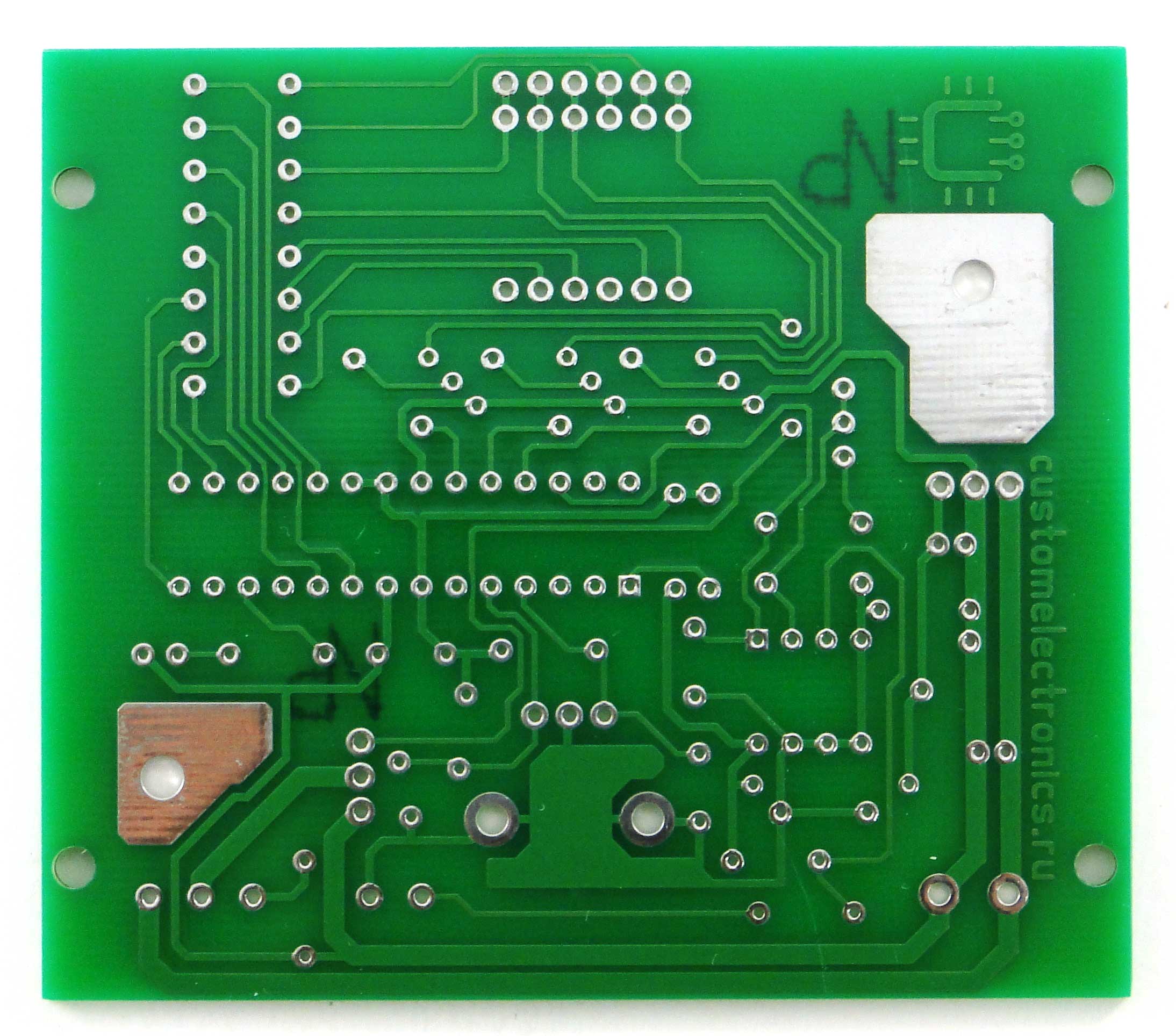
Printed circuit board
The printed circuit board is single-sided with four jumpers. The PCB file can be downloaded at the end of the article.

Printed circuit board. Front side

Printed circuit board. back side
List of components
To assemble the printed circuit board and housing, you will need the following components and materials:
- BQ1. Encoder EC12E24204A8
- C1. Electrolytic capacitor 35V, 10uF
- C2, C4-C9. Ceramic capacitors X7R, 0.1uF, 10%, 50V
- C3. Electrolytic capacitor 10V, 47uF
- DD1. Microcontroller ATmega8A-PU in DIP-28 package
- DA1. L7805CV 5V stabilizer in TO-220 package
- DA2. Operational amplifier LM358DT in DIP-8 package
- HG1. Seven-segment three-digit indicator with a common cathode BC56-12GWA. The board also has a seat for a cheap analogue.
- HL1. Any indicator LED for a current of 20 mA with a pin pitch of 2.54 mm
- R2,R7. Resistors 300 Ohm, 0.125W - 2 pcs.
- R6, R8-R20. Resistors 1kOhm, 0.125W - 13pcs
- R3. Resistor 10kOhm, 0.125W
- R5. Resistor 100kOhm, 0.125W
- R1. Resistor 1MOhm, 0.125W
- R4. Trimmer resistor 3296W 100kOhm
- VT1. Field effect transistor IRF3205PBF in TO-220 package
- VT2-VT4. Transistors BC547BTA in TO-92 package - 3 pcs.
- XS1. Terminal for two contacts with pin spacing 5.08 mm
- Terminal for two contacts with pin spacing 3.81 mm
- Terminal for three contacts with pin spacing 3.81 mm
- Radiator for stabilizer FK301
- Housing socket DIP-28
- Housing socket DIP-8
- Soldering iron connector
- Power switch SWR-45 B-W(13-KN1-1)
- Soldering iron. We will write about it later
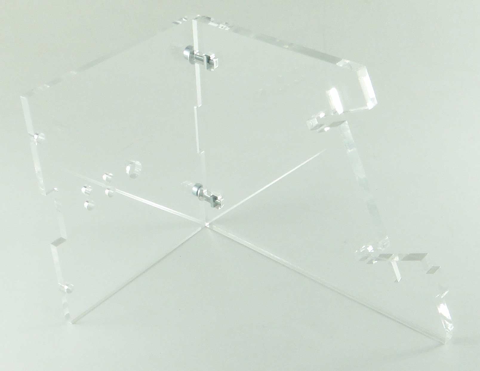
- Plexiglas parts for the body (cutting files at the end of the article)
- Encoder knob. You can buy it, or you can print it on a 3D printer. File for downloading the model at the end of the article
- Screw M3x10 - 2 pcs.
- Screw M3x14 - 4 pcs.
- Screw M3x30 - 4 pcs
- Nut M3 - 2 pcs.
- M3 square nut - 8 pcs
- Washer M3 - 8 pcs
- M3 locking washer - 8 pcs
- Assembly will also require installation wires, zip ties and heat shrink tubing.
This is what a set of all the parts looks like:

Set of parts for assembly of the Simple Solder MK936 soldering station
PCB installation
When assembling a printed circuit board, it is convenient to use the assembly drawing:

Assembly drawing of the printed circuit board of the Simple Solder MK936 soldering station
The installation process will be shown and commented on in detail in the video below. Let us note only a few points. It is necessary to observe the polarity of electrolytic capacitors, LEDs and the direction of installation of microcircuits. Do not install microcircuits until the case is completely assembled and the supply voltage has been checked. ICs and transistors must be handled carefully to avoid damaging them from static electricity. Once the board is assembled, it should look like this:

Soldering station printed circuit board assembly
Housing assembly and volumetric installation
The block wiring diagram looks like this:

Soldering station wiring diagram
That is, all that remains is to supply power to the board and connect the soldering iron connector. You need to solder five wires to the soldering iron connector. The first and fifth are red, the rest are black. You should immediately put a heat-shrink tube on the contacts, and tin the free ends of the wires. The short (from the switch to the board) and long (from the switch to the power source) red wires should be soldered to the power switch. Then the switch and connector can be installed on the front panel. Please note that the switch may be very difficult to engage. If necessary, modify the front panel with a file!


The next step is to put all these parts together. There is no need to install the controller, operational amplifier or screw on the front panel!

Assembling the soldering station housing
Controller firmware and setup
You can find the HEX file for the controller firmware at the end of the article. The fuse bits must remain factory-set, that is, the controller will operate at a frequency of 1 MHz from the internal oscillator. The first power-up should be done before installing the microcontroller and operational amplifier for a fee. Serve constant pressure supply from 12 to 24V (red should be “+”, black “-”) to the circuit and check that between pins 2 and 3 of the DA1 stabilizer there is a supply voltage of 5V (middle and right pins). After this, turn off the power and install the DA1 and DD1 chips into the sockets. At the same time, monitor the position of the chip key. Turn on the soldering station again and make sure that all functions work correctly. The indicator displays the temperature, the encoder changes it, the soldering iron heats up, and the LED signals the operating mode. Next, you need to calibrate the soldering station. The best option for calibration is to use an additional thermocouple. It is necessary to set the required temperature and control it on the tip using a reference device. If the readings differ, then adjust using the multi-turn trimming resistor R4. When adjusting, remember that the indicator readings may differ slightly from the actual temperature. That is, if you set, for example, the temperature to “280”, and the indicator readings deviate slightly, then according to the reference device you need to achieve exactly a temperature of 280°C. If you don’t have a control one at hand measuring instrument, then you can set the resistor resistance to about 90 kOhm and then select the temperature experimentally. After the soldering station has been checked, you can carefully install the front panel so that the parts do not crack.

Soldering station assembly

Soldering station assembly
Video of work
We made a short video review …. And detailed video, which shows the build process:
Conclusion
This simple soldering station will greatly change your soldering experience if you have soldered before with a regular corded soldering iron. This is what it looks like when the assembly is complete. A few more words need to be said about the soldering iron. This is the simplest soldering iron with a temperature sensor. It has a regular nichrome heater and the cheapest tip. We recommend that you immediately purchase a replacement tip for it. Any with an outer diameter of 6.5mm, an inner diameter of 4mm, and a shank length of 25mm will do.

Soldering iron disassembled with spare tip
Downloads
Printed circuit board in Sprint Layout formatFirmware for microcontrollerFile for cutting plexiglassModel of encoder handle for 3D printing
UPD
The files posted above are outdated. IN current version We updated the drawings for cutting plexiglass, making the circuit board, and also updated the firmware to remove the flickering indicator. Please note that for new version firmware, you need to enable CKSEL0, CKSEL2, CKSEL3, SUT0, BOOTSZ0, BOOTSZ1 and SPIEN (that is, change the standard settings). Printed circuit board in Sprint Layout V1.1 format Firmware for microcontroller V1.1 File for cutting plexiglass V1.1
This soldering station can also be purchased as a kit for self-assembly in our store and at our partners GOOD-KITS.ru and ROBOTCLASS.ru.
Compound: ATmega8, LM358, IRFZ44, 7805, bridge, 13 resistors, one potentiometer, 2 electrolytes, 4 capacitors, three-digit seven-segment LED indicator, five buttons. Everything is placed on two boards measuring 60x70mm and 60x50mm, located at an angle of 90 degrees.
I purchased the soldering iron from soldering stations ZD-929, ZD-937.

The soldering iron has a ceramic heater and a built-in thermocouple.
Soldering iron connector pinout for ZD-929:

Functional:
Temperature from 50 to 500 degrees, (heating to 260 degrees for about 30 seconds), two buttons +10 degrees and -10 degrees temperature, three memory buttons - long press (until blinking) - remembering the set temperature (EE), short - setting the temperature from memory. After power is applied, the circuit sleeps; after pressing the button, the installation from the first memory cell is turned on. When you first turn on the temperature in memory is 250, 300, 350 degrees. The set temperature blinks on the indicator, then the tip temperature runs and then lights up with an accuracy of 1 g in real time (after heating, it sometimes runs 1-2 g ahead, then stabilizes and occasionally jumps by +-1 g). 1 hour after the last manipulation of the buttons, it falls asleep and cools down (protection against forgetting to turn it off). If the temperature is more than 400 degrees, he falls asleep after 10 minutes (to preserve the sting). The beeper beeps when turned on, when buttons are pressed, when recording into memory, when the set temperature is reached, it warns three times before falling asleep (double beep), and when falling asleep (five beeps).
Element ratings:
R1 - 1M
R2 - 1k
R3 - 10k
R4 - 82k
R5 - 47k
R7, R8 - 10k
R indicator -0.5k
C3 - 1000mF/50v
C2 - 200mF/10v
C - 0.1mF
Q1 - IRFZ44
IC4 - 7805
1. The transformer and diode bridge are selected based on the supply voltage and power of the soldering iron used. For me it is 24 V / 48 W. To obtain +5 V, a linear stabilizer 7805 is used. Or a transformer with a separate winding is needed to power the digital part with a voltage of 8-9 V. I got a power supply from some old branded computer - DELTAPOVER, pulse generator, 18 volts, 3 amperes, size like two packs of cigarettes, works great, even without a cooler.
2. Field-effect transistor at the PWM output - any suitable one (I have IRFZ44).
3. The first LED I came across in a radio store, I was disappointed when I called at home and found out that the sign segments inside were not parallel, so the board became more complicated. It is marked on the side “BT-C512RD” and lights up green. You can use any indicator or three with appropriate adjustments to the board, and if the anode is common, then the firmware (firmware option below).
4. A beeper with a built-in generator, connects + to the 14th leg of the mega, - to the minus power supply (not on the diagram or board, because I came up with it later).

5. Purpose of the buttons:
S1: On / -10°C
S2: +10gr.С
S3: Memory 1
S4: Memory 2
S5: Memory 3
4. A beeper with a built-in generator, connects + to the 14th leg of the mega, - to the minus power supply (not on the diagram or board, because I came up with it later).

Now about the firmware. Of all those that took place during development, 2 final options are relevant:
1. For LEDs with a common cathode.
2. For LEDs with a common anode.
Now about the firmware. Of all those that took place during development, 2 final options are relevant: 1. For LEDs with a common cathode.
2. For LED with

DIY digital soldering station (ATmega8, C)
27.05.2012
Composition: ATmega8, LM358, IRFZ44, 7805, bridge, 13 resistors, one potentiometer, 2 electrolytes, 4 capacitors, three-digit LED seven-segment...
DIY soldering station. How to assemble a soldering station with a hair dryer for little money.

It is often necessary to repair devices with SMD components (phones, radios, various modules), etc. The same USB connector on a phone (as often happens) is not so easy to re-solder with a regular soldering iron without damage. So it's time to start assembling the soldering station.

Below is a list of the main components that will be needed to assemble a “budget soldering station”.
Buy on AliExpress

The scheme is primitive. The author also suggests source firmware in C++.
The author's printed circuit board is made for SMD resistors and capacitors. I decided to remake it for output components (partially). I separated the high-voltage part from main board and assembled it separately.


I transferred the printed circuit board to PCB using the “LUT” technology and etched it with ferric chloride. I installed the transistor that controls the turbine on the hot air gun, KT805, and made sure to install it on a small heat sink.

Since this is a “budget version,” I decided not to buy the case, but to make it myself. I had a casing lying around, with fairly thick and high-quality plastic from an old German TV, and I decided to cut the walls and assemble a housing from it for a “soldering station.” Everything looks pretty good.


I trimmed the LEDs on the front panel so they wouldn't stick out.

I didn't buy a soldering iron either. I had a Chinese “soldering iron gun” with a burnt-out heater, and a handle from a Soviet soldering iron. I just took the sleeve - which holds the tip and the heater from the "soldering iron - gun" - and connected them together with the handle, bought a heater with a thermocouple and inserted it into it.


I got the transformer from a Soviet 25-volt tape recorder, and it’s quite suitable in terms of power. The diode bridge was assembled from KD202 diodes. Installed more active cooling(exhaust fan).


If you look at my board assembly in the photo, you will see a part that is not in the original seals. This is my “multivibrator”. Why is he needed there? Ehh.. I installed it for a buzzer (squeaker) because I didn’t have a buzzer with a built-in generator, and I really wanted a beeping sound. In fact, I don't recommend you do this! That's a lot of extra hesitation. It's easier to buy a buzzer with a built-in generator.
It is necessary to take into account that the author divided the power supply into digital and power. This is necessary so that the microcontroller does not have interference or any interference from the power part. So in the circuit there are TWO EARTHS and the digital part is powered by a separate stabilized 5 volt power supply. I, like the author, also decided to use Charger from a mobile phone.

Let's take it AVR programmer USBAsp. We connect it to the PC and to the microcontroller.
A soldering iron is the main tool for those who are at least somehow connected with electronics. But most ordinary soldering irons are only suitable for soldering pans; a more or less normal soldering iron with a thermostat and replaceable tips is not cheap, and there is nothing to say about soldering stations. I propose to assemble a simple soldering station that is not very different in functionality from the serial ones.
Scheme
The microcontroller works like a thermostat: it receives data from the thermal converter and controls the transistor, which in turn turns on the heater. The set and current temperature of the soldering iron are displayed on a seven-segment indicator. Buttons S1-S4 are used to set the temperature in steps of 100°C and 10°C, S5-S6 - to turn the station on and off (standby mode), S7 - switches the temperature display mode: the current temperature or the set one (in this mode it can be changed ). The operation of the heater is indicated by LED1. In the event of a power failure, the last set temperature is stored in the non-volatile EEPROM memory and the next time it is turned on, the station begins heating to this temperature.Details
The station uses an 18V 40W network transformer, any diode bridge capable of withstanding a current of 2A and reverse voltage 30V, for example KTs410. The 7805 integrated voltage stabilizer must be screwed to a radiator that is at least the size of a matchbox. Filter capacitors C1 are electrolytic at 100-500 μF, C2 can be removed if desired. Indicator - any three-digit indicator with dynamic indication and a common anode; it is better to hide it behind a light filter. Current limiting resistors R8-R11 with a resistance of 330 Ohm-1 kOhm. Buttons S1-S6 without locking, preferably tactile, S7 - toggle switch or button, but with locking. Resistors R1-R7 - any, with a resistance of 10 kOhm-100 kOhm. Transistor T1 - N-channel MOSFET, controlled by logic level, permissible voltage drain-source not less than 25V and current not less than 3A, for example: IRL3103, IRL3713, IRF3708, IRF3709, etc. ATmega8 microcontroller with any suffix and housing (on the diagram there are pin numbers for the DIP housing). Of the fuses, we change only CKSEL: we set CKSEL3...0=0100 to the internal 8 MHz oscillator, we do not touch the rest. This scheme does not require any configuration and works immediately (if it is assembled correctly).Soldering iron
The circuit provides for the use of soldering irons used in commercially produced soldering stations, for example Lukey or AOYUE. Such soldering irons are sold as spare parts and are slightly more expensive than the previously mentioned pot soldering irons. The main difference that concerns us is the type of temperature sensor, it can be a thermistor or thermocouple. We need the first one. This type of converter is suitable for soldering irons that have a HAKKO 003 (HAKKO A1321) ceramic heating element inside. An example of such a soldering iron is used in soldering stations Lukey 868, 852D+, 936, etc. This soldering iron is more expensive, but is considered to be of higher quality.Finally
Lukey soldering irons have a PS/2 connector for connecting the station, while AOYUE has a connector similar to the old Soviet one for connecting a tape recorder. You can find their pinout on the Internet, or you can simply cut off the connector and solder it directly to the board. To find out which wire is which, you can measure the resistance: the heater will have about 3 ohms, and the thermistor will have about 50 ohms (at room temperature).Almost all modern soldering irons for soldering stations have the ability to ground the tip; use it to protect the soldered parts from static discharges.
And here's what happened
Everything was soldered using EPSN with copper wire wound around the tip. I didn’t think about miniaturization then.


The insides were photographed two years ago, when it was first made, so attentive readers may notice a relay (replaced by a transistor) and a thermocouple converter (red resistors and a trimmer in the lower left corner).
There are a lot of diagrams of various soldering stations on the Internet, but they all have their own characteristics. Some are difficult for beginners, others work with rare soldering irons, others are not finished, etc. We focused specifically on simplicity, low cost and functionality, so that every novice radio amateur could assemble such a soldering station.
eldigi.ru
An ordinary soldering iron, which is connected directly to the network, simply heats constantly with the same power. Because of this, it takes a very long time to warm up and there is no way to regulate the temperature in it. You can dim this power, but achieving a stable temperature and repeatable soldering will be very difficult.
A soldering iron prepared for a soldering station has a built-in temperature sensor and this allows you to apply maximum power to it when heating up, and then maintain the temperature according to the sensor. If you simply try to regulate the power in proportion to the temperature difference, then it will either warm up very slowly, or the temperature will fluctuate cyclically. As a result, the control program must necessarily contain a PID control algorithm.
In our soldering station, we, of course, used a special soldering iron and paid maximum attention to temperature stability.
Specifications
- Powered by 12-24V DC voltage source
- Power consumption, when powered 24V: 50W
- Soldering iron resistance: 12ohm
- Time to reach operating mode: 1-2 minutes depending on supply voltage
- Maximum temperature deviation in stabilization mode, no more than 5 degrees
- Control algorithm: PID
- Temperature display on a seven-segment indicator
- Heater type: nichrome
- Temperature sensor type: thermocouple
- Temperature calibration capability
- Setting the temperature using the ecoder
- LED to display soldering iron status (heating/operating)
Schematic diagram
The scheme is extremely simple. At the heart of everything is the Atmega8 microcontroller. The signal from the optocoupler is fed to an operational amplifier with adjustable gain (for calibration) and then to the ADC input of the microcontroller. To display the temperature, a seven-segment indicator with a common cathode is used, the discharges of which are switched on through transistors. When rotating the BQ1 encoder knob, the temperature is set, and the rest of the time the current temperature is displayed. When turned on, the initial value is set to 280 degrees. Determining the difference between the current and required temperature, recalculating the coefficients of the PID components, the microcontroller heats up the soldering iron using PWM modulation.
To power the logical part of the circuit, a simple 5V linear stabilizer DA1 is used.

Printed circuit board
The printed circuit board is single-sided with four jumpers. The PCB file can be downloaded at the end of the article.

List of components
To assemble the printed circuit board and housing, you will need the following components and materials:
- BQ1. Encoder EC12E24204A8
- C1. Electrolytic capacitor 35V, 10uF
- C2, C4-C9. Ceramic capacitors X7R, 0.1uF, 10%, 50V
- C3. Electrolytic capacitor 10V, 47uF
- DD1. Microcontroller ATmega8A-PU in DIP-28 package
- DA1. L7805CV 5V stabilizer in TO-220 package
- DA2. Operational amplifier LM358DT in DIP-8 package
- HG1. Seven-segment three-digit indicator with a common cathode BC56-12GWA. The board also provides a seat for a cheap analogue.
- HL1. Any indicator LED for a current of 20 mA with a pin pitch of 2.54 mm
- R2,R7. Resistors 300 Ohm, 0.125W - 2 pcs.
- R6, R8-R20. Resistors 1kOhm, 0.125W - 13pcs
- R3. Resistor 10kOhm, 0.125W
- R5. Resistor 100kOhm, 0.125W
- R1. Resistor 1MOhm, 0.125W
- R4. Trimmer resistor 3296W 100kOhm
- VT1. Field effect transistor IRF3205PBF in TO-220 package
- VT2-VT4. Transistors BC547BTA in TO-92 package - 3 pcs.
- XS1. Terminal for two contacts with pin spacing 5.08 mm
- Terminal for two contacts with pin spacing 3.81 mm
- Terminal for three contacts with pin spacing 3.81 mm
- Radiator for stabilizer FK301
- Housing socket DIP-28
- Housing socket DIP-8
- Power switch SWR-45 B-W(13-KN1-1)
- Soldering iron. We will write about it later
- Plexiglas parts for the body (cutting files at the end of the article)
- Encoder knob. You can buy it, or you can print it on a 3D printer. File for downloading the model at the end of the article
- Screw M3x10 - 2 pcs.
- Screw M3x14 - 4 pcs.
- Screw M3x30 - 4 pcs.
- Nut M3 - 2 pcs.
- M3 square nut – 8 pcs
- M3 washer - 8 pcs
- M3 locking washer – 8 pcs
- Assembly will also require installation wires, zip ties and heat shrink tubing.
This is what a set of all the parts looks like:

PCB installation
When assembling a printed circuit board, it is convenient to use the assembly drawing:

The installation process will be shown and commented on in detail in the video below. Let us note only a few points. It is necessary to observe the polarity of electrolytic capacitors, LEDs and the direction of installation of microcircuits. Do not install microcircuits until the case is completely assembled and the supply voltage has been checked. ICs and transistors must be handled carefully to avoid damage from static electricity.
Once the board is assembled, it should look like this:

Housing assembly and volumetric installation
The block wiring diagram looks like this:

That is, all that remains is to supply power to the board and connect the soldering iron connector.
You need to solder five wires to the soldering iron connector. The first and fifth are red, the rest are black. You must immediately put a heat-shrinkable tube on the contacts, and tin the free ends of the wires.
The short (from the switch to the board) and long (from the switch to the power source) red wires should be soldered to the power switch.
The switch and connector can then be installed on the front panel. Please note that the switch may be very difficult to engage. If necessary, modify the front panel with a file!

The next step is to put all these parts together. There is no need to install the controller, operational amplifier or screw on the front panel!

Controller firmware and setup
You can find the HEX file for the controller firmware at the end of the article. The fuse bits should remain factory, that is, the controller will operate at a frequency of 1 MHz from the internal oscillator.
The first power-up should be done before installing the microcontroller and operational amplifier on the board. Apply a constant supply voltage from 12 to 24V (red should be “+”, black “-”) to the circuit and check that there is a 5V supply voltage between pins 2 and 3 of the DA1 stabilizer (middle and right pins). After this, turn off the power and install the DA1 and DD1 chips into the sockets. At the same time, monitor the position of the chip key.
Turn the soldering station back on and make sure all functions are working correctly. The indicator displays the temperature, the encoder changes it, the soldering iron heats up, and the LED signals the operating mode.
Next, you need to calibrate the soldering station.
The best option for calibration is to use an additional thermocouple. It is necessary to set the required temperature and control it on the tip using a reference device. If the readings differ, then adjust the multi-turn trimmer resistor R4.
When setting, remember that the indicator readings may differ slightly from the actual temperature. That is, if you set, for example, the temperature to “280”, and the indicator readings deviate slightly, then according to the reference device you need to achieve exactly a temperature of 280°C.
If you don’t have a control measuring device at hand, you can set the resistor resistance to about 90 kOhm and then select the temperature experimentally.
After the soldering station has been checked, you can carefully install the front panel so that the parts do not crack.


Video of work
We made a short video review
…. and a detailed video showing the assembly process: