Download usb rs232 adapter circuit diagrams. DIY USB-COM adapter: diagram, device and recommendations
In this topic, we will consider a selection of several amateur radio circuits that allow you to assemble a USB COM adapter, which is often used in measuring and medical equipment. An outdated but still relevant RS-232 serial port, also known as a COM port, is used to exchange information between a computer and a device. It is called sequential because data is exchanged bit by bit one at a time.
USB COM adapter to FT8U232BM |

The base of the adapter is microassembly FT8U232BM. It supports all levels required by the COM port standard (DCD, RX, TX, DTR, GND, DSR, RTS, CTS, RI) according to the pinout.

To match the TTL levels of RS232 with FT8U232BM, 74HC00 microassemblies are used. The 93C46 chip is used to store the personal number (PID), manufacturer code (VID) and serial number of the device. Therefore, it can be excluded, but then only one device can be connected to the adapter, creating a virtual COM port. You can download driver reference documentation for working with a computer and a printed circuit board drawing from the green link above.
Simplified version
It only supports RX, TX, RTS, CTS signal chains. To match the levels, a fairly well-known MAX232 chip is used.
The PL2303HX is a nearly complete USB to RS232 converter. The design uses a MAX232 transceiver that converts the RX, TX levels.

There are two options for the USB COM chip adapter: new (var D 2012) and old (var A 2004). According to the reference book, their pinouts are different, so you need to check which version of the microassembly you have.
The PL2303 completely replaces the COM port, but most often only the Tx and Rx pins are used. To interface levels between the USB and COM ports, I use the well-known MAX232 chip. It is needed because in a typical COM port the logical levels are 12 volts, while USB works with lower levels.
To work with the adapter, you need to install a driver for a virtual COM port in your computer's operating system; it can be downloaded from the link above.
To check the functionality of the circuit, you can close the contacts that convert the Rx Tx levels and send some data to the COM port, it should be returned. Excellent for port monitoring.
The Attiny2313 is powered by . The circuit only supports Rx and Tx control signals.

The firmware for the microcontroller, a drawing of the adapter printed circuit board, a terminal program for checking the device, a driver and fuses can be downloaded from the link above.
When you connect the interface to your computer, the message “Found new hardware” should appear. We install the driver using the standard algorithm and the entire device is ready for use. To check the functionality, briefly short-circuit the Rx and Tx pins and use the terminal program to set the COM port number and send any message. If the adapter is working, a message should appear in the program window.
This article provides a selection of circuits that allow you to assemble a simple but extremely useful device: Com adapter.
A serial port (RS-232), or as it is also called a COM port, is designed for exchanging information between a computer and peripheral devices. It was called serial because data exchange through it occurs bit by bit one at a time.
Initially, the COM port was intended to connect the modem to a computer. Later they began to connect a mouse, scanner and other peripherals to it. It is also possible to organize a direct connection of two computers using the COM port.
Today, the vast majority of computers are not equipped with an RS-232 connector, since the USB standard has become widespread. But there are still many external devices that work only with a COM port (various programmers, diagnostic equipment, receivers, etc.). The way out of this situation is to use a COM-USB adapter device. Below are several options for the most popular circuits of this adapter.
Full adapter - COM adapter for USB port
on the FT8U232BM chip
The basis of this circuit is the FT8U232BM microcircuit - manufactured by FIDI Ltd. A device built according to this scheme supports all signal levels (DCD, RX, TX, DTR, GND, DSR, RTS, CTS, RI) according to the COM port pinout.

Operating voltage: 3.3...5.5 V, interface: TX RX VCC GND...

 To match the TTL levels of the RS232 interface with the levels of the FT8U232BM microcircuit, two 74HC00 microcircuits are used. The 93C46 memory chip is designed to store a personal number (PID), manufacturer code (VID), as well as the serial number of the device. This microcircuit may not be installed. In this case, it will be possible to connect only 1 device creating a virtual COM port to the computer. The AT93C46 memory chip can be replaced with AT93C66, AT93C56. 93C46 is flashed directly on the board using the manufacturer's proprietary FTDI utility.
Simplified version on FT8U232BM
This is a circuit of a simplified USB-COM adapter that supports only RX, TX, RTS, CTS RS232 interface signal lines. To match the levels of the com port with the digital levels of the FT8U232BM, a .

Adapter diagram for COM from USB to PL2303
The following circuit is based on the PL2303HX chip, which is a USB to RS232 interface converter. Manufacturer PL2303HX - Taiwanese company Prolific. This circuit also uses a MAX232 transceiver that converts RX, TX signals.
For proper operation, you must install a driver for the virtual COM port. To do this, download and install the driver from the link below.
Then we configure the virtual port: set the “flow control” window to NO. Then select a free port number.

USB - COM adapter on Attiny2313 microcontroller
 Power is supplied directly from the USB power bus. The entire circuit is assembled on a single-sided board (SMD and TN options). The device only supports Rx and Tx signals.

The firmware for the adapter, the printed circuit board drawing (SMD and TH), as well as the terminal program for checking the adapter can be downloaded from the link below:
When , fuses must be set as follows:

For the device to operate, you must install a virtual COM port driver. To do this, download it:
Now we insert our adapter into the computer’s USB port, the computer should display the message “Found a new device”, and then offer to install a driver for it. Select “Install from a specified location” and click on the “Next” button. Then in a new window, select the path to the folder of the downloaded and unpacked driver and again click the “Next” button. After a few seconds, the driver will be installed and the device will be ready to use.
To check the functionality of the device, we temporarily close the Rx and Tx pins and from the terminal program, also located in the archive, set the COM port number and send any message. To do this, write, for example, “Hello” and press the “Send” button. If the adapter is working, the written message will appear in the upper window of the program.

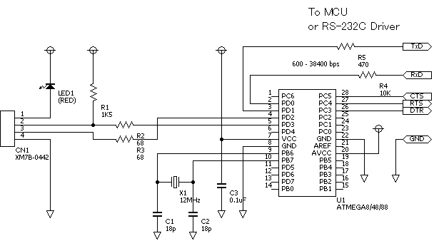
COM-USB adapter on Atmega8 microcontroller
Another COM-USB adapter circuit, now on the Atmega8 microcontroller (Atmega48, Atmega88). The circuit provides processing of Rx, Tx, DTR, RTS, CTS signals of the RS232 interface. The virtual port driver for this circuit is the same as for the attiny2313 adapter.
Firmware for atmega8/48/88 and PCB drawing can be downloaded from the following link:
Fuses when programming for atmega8/48/88:

The holidays are finally over and it's time to do something.
Let's start, perhaps, with a necessary device that makes the life of an ordinary electronics engineer easier - a communication device with a computer. This is necessary in order to transfer data to the computer (temperature from sensors, door position, engine speed, table of values from the recorder...) or receive data from the computer (tables of values for calculations, configuration data for devices, new firmware for the bootloader...) . For debugging a new device (to see what is happening there, in the brains of the microcontroller), it is generally an irreplaceable thing.
As you know, there are many interfaces through which a microcontroller can communicate with the outside world. But when it comes to communication with a computer, the RS-232 interface (COM port) is beyond competition. The reason is the ease of working with the port from the computer side and the availability of a large number of programs designed for this. In addition, almost every microcontroller has a hardware-supported USART interface (this is the same RS-232, only with voltages 0 - 5v), which makes the communication process easy to implement.
In order to bring the signal levels of the microcontroller USART to the levels of the computer COM port, you need to assemble a simple converter (for example, on MAX232), but you can take a more interesting path
A more interesting way is to assemble a UART to USB converter. In this case, the USB port is perceived by the computer as a virtual COM port. In this case, we kill several birds with one stone:
– There is a USB port in any computer (although a COM port is still quite common, but it is no longer found on laptops);
– as it turned out, a UART to COM (RS-232) converter is much more difficult to make than a UART to USB (I made a programmer for the COM port twice with a MAX232 converter - both times it was unsuccessful);
– if you connect the converter via a USB hub, then we get several virtual COM ports on one USB, plus security for the computer, since the hub acts as a buffer.
Here is the UART to USB converter circuit.
This is not my device. This diagram was taken from the site www.recursion.jp/avrcdc/. The reason I present it here is the simplicity of the circuit and low cost of production. Assembling the circuit is quite simple (you can even use a breadboard).

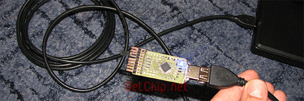
I made the finished device in the form of a “flash drive” in order to make it more convenient to use in “field” conditions. For greater comfort, you can take a USB extension cable, attach it to your computer with one connector, insert our “flash drive-converter” into the second, and we’ll get a mobile device that can be connected to any circuit without any problems.
Double-sided printed circuit board, suitable for ATmega8/48/88/168 microcontrollers
Here is an option for manufacturing using the technology described
Firmware for various microcontrollers:
Fuses for CodeVisionAVR, PonyProg are installed inversely
The SPI interface for the programmer is displayed along with all the interfaces on the back of the flash drive - we connect the programmer right there. We solder the reset pin near the reset pin (so as not to interfere). When programming, the converter must be powered with a voltage of 5v from the interfaces. Via USB is not advisable, since the supply voltage through the LED will decrease. If problems arise due to high noise, we hang a resistor that pulls up the power supply on the reset pin (5-10 kOhm). The presence of an LED is mandatory - it is used as a voltage regulator. The firmware provides for the operation of control lines (CTS, RTS, DTR), but they are not needed for UART and I did not output them to the interface connector. If you need them, you just need to “throw” jumpers from the legs of the microcontroller to the legs of the interface connector.
After the device is assembled,
you need to install a virtual COM port driver.
The archive contains folders for different Wins:
/raw - for (Windows 2000/XP)
/w2k - for Windows 2000 (bulk mode only)
/xpvista7 - for Windows XP/Vista/7 x32
/vista64 - for Windows Vista x64
This is done very simply:

1
Insert the “flash drive” into the USB port;

2
We receive a message in the tray that a new device has been found;

3
The “Found New Hardware Wizard” will launch, select “Install from a specified location”, click “Next”;

4
Select “Include the following search location” and in the window indicate the desired path to the driver;
5
Click “Next”, the driver will be installed, click “Finish”
Now in the “Properties” of “my computer” in the “Hardware” tab, click the “Device Manager” button. In the Device Manager window, in the “Ports (COM and LPT)” section, we will see a new device - "Virtual Communications Port (COM5)".

Each USB port will have its own virtual COM port (COM5, COM6, COM7, etc.).
Ready! Now you can use the converter.
Let's check the functionality of the converter; to do this, you need to short-circuit the input with the output (RxD, TxD) and send messages from the computer via the virtual port. Sent messages should be returned as received.
 We attach a jumper to the required pins. We launch the program to work with the COM port. You can use the standard Windows hyperterminal, but I prefer another program - small, portable and functional.
We launch the program, set the required port (look at the port number in the device manager), leave the speed and other parameters as they are, click “Connect”, in the window next to the “->Send” button, write a message, click “->Send” and see the result . The lower window is a sent message, the large window is a received message. If everything works, the messages will be the same.

This “flash drive – interface converter” will later turn into I2C toUSB, SPI to USB, SPI to UART, etc. you just need to reflash it with the necessary firmware. (I’m starting to notice a craving for universalization in myself :)).

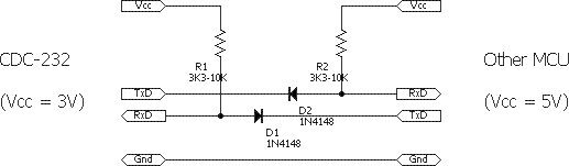
P.S. The source site recommends connecting them through a matching circuit to match the voltage levels of the converter (3.3v) and the device (5v). But I think resistors within half a kilo-ohm in the RxD, TxD lines should be enough for matching - you need to try.
P.P.S. This is the first practical scheme in the blog - there will be more of them later, since we seem to have figured out the basics (there are still some questions left - I will write little by little).
(Visited 31,429 times, 4 visits today)
DIY USB - COM (RS232) adapter - an article in which I will tell you how to make a simple adapter in just one evening. This adapter, by the way, is compatible with the CPU 166 P processor module. - a book that can be useful in amateur radio practice.
Here's what you'll need for the adapter:
|
Position designation |
Name |
Analog/replacement |
|
Ceramic capacitor - 0.1 μFx50V |
SMD size 0805 |
|
|
Ceramic capacitor - 33pFx50V |
SMD size 0805 |
|
|
Chip MAX232 |
ADM232 SOIC16 package |
|
|
Indicator LEDs with a diameter of 3mm. |
||
|
Ready module - USB-COM adapter (TTL levels) on the FT232 chip |
||
|
Resistor 0.125W 270 Ohm |
SMD size 0805 |
|
|
Resistor 0.125W 510 Ohm |
||
|
Resistor 0.125W 100 Ohm |
||
|
DB9 male plug |
||
|
Paid plug 3 contacts |
And also clips for the LEDs, a small plastic case, some wires and silicone glue.
Picture 1.
If TTL levels are sufficient for your purposes, then a ready-made board on the FT232 chip will be sufficient (the red board in Figure 1), and if you need to get levels close to the protocol levels, read on!
The first thing I did was attach the LEDs to the front side of the case using clips.

Figure 2

Figure 3.

Figure 4.

Figure 5.
The board has ready-made pads with all signals (according to the RS232 protocol, only TTL levels), as well as power supply and contacts for the RX and TX LEDs. Using this board, you can make a complete USB-COM adapter. I don’t need a full adapter, I limited myself to the RX and TX signals, and also used the signals to connect the LEDs. In order to convert TTL levels to those close to those of the RS232 protocol, you need to use a MAX232 buffer chip, but more on that a little later.

Figure 6
The board mentioned above was glued to the base of the case using silicone glue.

Figure 7
When the glue had dried, I soldered the LEDs to limit the current using 270 Ohm resistors.

Figure 8
On one of the old boards I came across a ready-made fragment with all the necessary wiring for the MAX232. All that remained was to cut it out and solder the chip.

Figure 9

Figure 10
I didn’t find the MAX232 microcircuit at hand; instead, I soldered in an analogue - ADM232.

Figure 11
I pasted insulating material on both sides. I used silicone glue.

Figure 12

Figure 13
The glue has dried. The next thing was to glue the resulting “sandwich” into the body.

Figure 14
I soldered the boards together according to the diagram, and also soldered and secured the DB9 connector.

Figure 15
I checked everything. Fully assembled USB-COM(RS232) adapter.

RS-232 is a popular protocol used to communicate between computers and modems and other peripheral devices. This is an interface for transmitting information between two devices over a distance of up to 20 m. Information is transmitted over wires with signal levels different from standard 5V to provide greater immunity to interference. Asynchronous data transfer is carried out at a set speed when synchronized by the level of the start pulse signal.
Serial interface RS-232 - standard overview
It is a widely used serial interface for synchronous and asynchronous data transmission, defined by the EIA RS-232-C standard and V.24 CCITT recommendations. It was originally created to connect a computer with a terminal. Currently used in a variety of fields.
The RS-232-C interface connects two devices. The transmission line of the first device is connected to the reception line of the second and vice versa (full duplex). To control the connected devices, software confirmation is used (introducing the corresponding control characters into the transmitted data stream). It is possible to organize hardware confirmation by organizing additional RS-232 lines to provide status determination and control functions.


| Standard | EIA RS-232-C, CCITT V.24 |
| Transmission speed | 115 Kbps (maximum) |
| Transmission distance | 15 m (maximum) |
| Character of the signal | asymmetrical in voltage |
| Number of drivers | 1 |
| Number of receivers | 1 |
| Connection diagram | full duplex, point to point |
The order of exchange via the RS-232C interface:
| Name | Direction | Description | Contact (25-pin connector) | Contact (9-pin connector) |
| DCD | IN | Carrier Detect | 8 | 1 |
| RXD | IN | Receive Data | 3 | 2 |
| TXD | OUT | Transmit Data | 2 | 3 |
| DTR | OUT | Data Terminal Ready | 20 | 4 |
| GND | - | System Ground | 7 | 5 |
| DSR | IN | Data Set Ready | 6 | 6 |
| RTS | OUT | Request to Send | 4 | 7 |
| CTS | IN | Clear to Send | 5 | 8 |
| R.I. | IN | Ring Indicator | 22 | 9 |
The RS-232C interface is designed for connecting standard external devices (printer, scanner, modem, mouse, etc.) to a computer, as well as for connecting computers with each other. The main advantages of using RS-232C over Centronics are:
- the ability to transmit over significantly longer distances;
- much simpler connecting cable.
- See diagram
The purpose of the signals is as follows:
- FG - protective grounding (screen).
- TxD - data transmitted by a computer in serial code (negative logic).
- RxD - data received by the computer in serial code (negative logic).
- RTS - transmission request signal. Active during the entire transmission.
- CTS is a reset (clear) signal for transmission. Active during the entire transmission. Indicates that the receiver is ready.
- DSR - data readiness. Used to set the modem mode.
- SG - signal ground, neutral wire.
- DCD - data carrier detection (detection of the received signal).
- DTR - output data readiness.
- RI - call indicator. Indicates that the modem is receiving a call signal over the telephone network.

For a two-wire communication line, in the case of only transmission from a computer to an external device, the SG and TxD signals are used. All 10 interface signals are activated only when connecting a computer to a modem.
The format of the transmitted data is shown in the figure below. Actually, the data (5, 6, 7 or 8 bits) is accompanied by a start bit, a parity bit and one or two stop bits. Having received the start bit, the receiver selects data bits from the line at certain time intervals. It is very important that the clock frequencies of the receiver and transmitter are the same, the permissible discrepancy is no more than 10%). The RS-232C transmission speed can be selected from the following range: 110, 150, 300, 600, 1200, 2400, 4800, 9600, 19200, 38400, 57600, 115200 bps.

All RS-232C signals are transmitted at specially selected levels, ensuring high noise immunity of communication (figure below). Note that the data is transmitted in inverse code (a logical one corresponds to a low level, a logical zero to a high level).
To connect an arbitrary device to a computer via RS-232C, a three- or four-wire communication line is usually used, but other interface signals can also be used.

Exchange via RS-232C is carried out using calls on specially designated ports:
- COM1 (addresses 3F8h...3FFh, interrupt IRQ4);
- COM2 (addresses 2F8h...2FFh, interrupt IRQ3);
- COM3 (addresses 3F8h...3EFh, interrupt IRQ10);
- COM4 (addresses 2E8h...2EFh, interrupt IRQ11).
RS-232 cable pinouts
Let's look at standard and not so standard cable pinouts.
Legend:
- F - “mother”;
- M - “dad”;
- “-” - connection;
- “x” - no connection;
- “+” - lines are combined.
Used to connect devices such as a computer and a modem.
Direct connection:
- 1 - 1
- 2 - 2
- 3 - 3
- 9 - 9
Note: The screens are connected.
DTE 9 F<-->DTE 9 F (Null-modem 9)
Used to connect devices such as computer and computer.
Compound:
- 1+7- 8
- 2 - 3
- 3 - 2
- 4 - 6
- 5 - 5
- 6 - 4
- 7+1 - 8
- 8 - 1+7
Note: Pins 1 and 7 on the connectors are connected to each other. 9 is not used. The screens are connected.
DTE 25 F<-->DCE 9 M
Used to connect devices such as a computer (25-pin connector) and a 9-pin mouse (or modem).
Compound:
- 2 - 3
- 3 - 2
- 4 - 7
- 5 - 8
- 6 - 6
- 7 - 5
- 8 - 1
- 20 - 4
- 22 – 9
Note:
DTE 9 F<-->DCE 25 M
Used to connect devices such as a computer (9-pin connector) and a 25-pin mouse (or modem).
Compound:
- 1 - 8
- 2 - 3
- 3 - 2
- 4 - 20
- 5 - 7
- 6 - 6
- 7 - 4
- 8 - 5
- 9 - 22
Note: The rest are not used. The screens are connected.
DTE 25 F<-->DCE 25 M
Used to connect devices such as a computer (25-pin connector) and a 25-pin mouse (or modem).
Direct connection:
- 1 - 1
- 2 - 2
- 3 - 3
- 4 - 4
- 24 - 24
- 25 – 25
Note: The screens are connected.
DTE 25 F<-->DTE 25 F (Null-modem Universal 25)
Used to connect devices such as a computer (25-pin connector) and a computer (25-pin connector).
Compound:
- 1 - 1
- 2 - 3
- 3 - 2
- 4 - 5
- 5 - 4
- 6+8 - 20
- 7 - 7
- 20 - 6+8
Note: The rest are not used. The screens are connected.
Plug for COM port 9 pin F
Compound:
- 1+6+4
Note: The rest are not used.
Plug for COM port 25 pin F
Used for testing communication applications.
Compound:
- 6+8+20
Note: The rest are not used.
How to get 5 volts from RS-232 port?

List of required parts:
- Linear regulator - L78L05.
- 2 rectifier diodes (D1, D2) - 1N4004.
- Electrolytic capacitor (C1) - 22 µF.
- Capacitor (C2) - 0.001 µF.
- 2 resistors (R1, R2) - 43 Ohm.
RS-232 interface converters
RS-232 to TTL converter
When developing various kinds of electronic devices using microcontrollers, it is often useful to be able to connect them to a personal computer via a serial port. However, this cannot be done directly, since according to the RS-232 standard the signal is transmitted in levels of -3...-15 V (logical<1>) and +3..+15V (logical<0>).
To convert RS-232 levels to standard TTL logic levels, special converter chips are usually used. However, it does not always make sense to include a level converter in the circuit of the device being designed, since it often happens that communication with a computer is needed only at the stage of manufacturing and debugging the device, and for the final product there is no need for it.