A good antenna for digital television with your own hands. Wireless connection
Digital television is broadcast in the UHF range. Therefore, you can use almost any UHF antenna. But I needed simple, easily repeatable and strong UHF antenna range.
Such that you could carry it with you, and on occasion you wouldn’t mind giving it to people for a small amount.
The basis was taken from the famous “ eight“, with the difference that I used it without a reflector.
The material for the antenna sheet can be any conductive material of suitable cross-section. It can be copper or aluminum wire with a thickness of 1 to 5 mm, a tube, strip, busbar, corner, profile... I took copper wire with a diameter of 3 mm. Easy to solder, easy to bend during assembly, easy to straighten if bent.
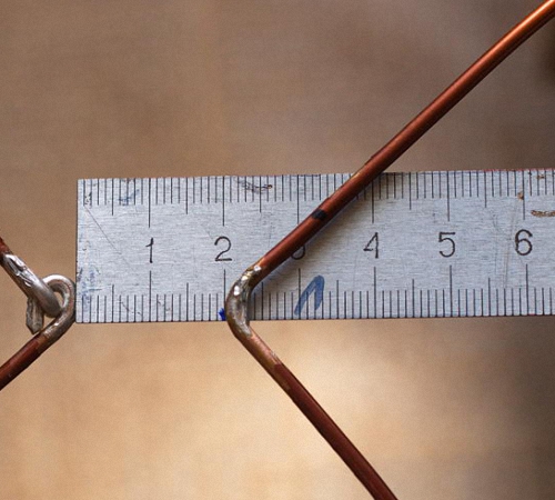
The outer side of the square is 14 cm, the inner side is slightly smaller - 13 cm due to the fact that the middle of the two squares does not converge, about 2 cm from corner to corner.
So, if you are not making an antenna from wire, then measure it this way - the top sides are 14 cm, the sides are 13.
All sizes are approximate. Don't be afraid to get shortchanged or make mistakes. Our plans do not include making an antenna that meets all standards. We need a simple but workhorse. A surrogate, but reliable. Surrogate because:
1
. Personally, I definitely couldn’t keep the sizes.
2
. There is no reflector.
3
. I took a 50 ohm cable instead of 75 ohm, but with a thick braid. Friends usually used this cable for car antennas for 27 MHz radio stations.
Nevertheless, the antenna works quite well.
U digital signal there is a feature, it either exists or it doesn’t. Upon admission analogue television, different channels showed from different levels interference, and when removed, the level of snow on the screen simply increased until the signal completely disappeared. In digital, the signal is almost the same on all channels, and if there is reception, then there is all channels.
I have tested this antenna on more than a dozen TVs in our region.
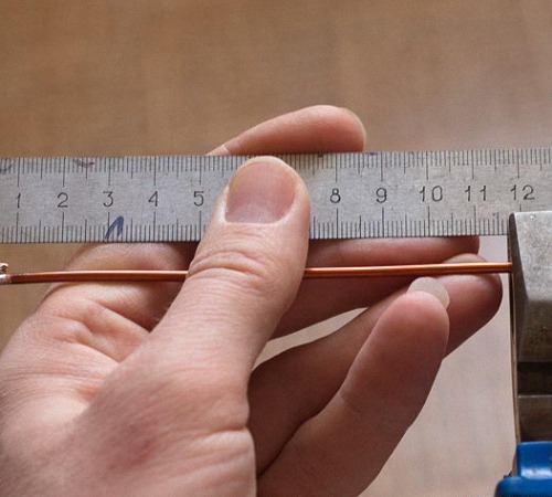
So. We measure a piece with a total length of 112 cm and bend the wire. The first section is 13 cm + 1 cm for the loop (for strength). The second and third are 14 cm each, the fourth and heels are 13 cm each, the sixth and seventh are 14 cm each, and the last eighth is 13 cm + 1 cm stiffening loop.
We strip 1.5 - 2 cm at both ends, twist the two loops behind each other, and then solder the joint. This will be one cable connection pin. After 2 cm another. It doesn’t matter where to solder the central core or the braid.

Solder spacing 2 cm
I took about three meters of cable. In most cases, it’s enough if you don’t do it for yourself personally. For yourself, measure out as much as you need.
I stripped the cable from the antenna side by two centimeters, to the plug - 1 cm. If the plug is like in the photo. You can take any, stronger.

Stripping the cable
The plug was cleaned with a file and a scalpel.

After sealing, both soldering points are filled with glue from a gun. On the plug, first hot glue is poured into the soldering area and into the plastic cap, with a reserve; the excess can then be removed. Then, before the glue cools down, everything quickly comes together. You can’t gnaw such a joint with your teeth. Reliable, at the same time elastic.
The soldering on the antenna itself is also filled with glue, but for the rigidity of the structure, a frame is taken - any lid, box, .... I took the cap from a 20-liter water bottle, of which I had accumulated a sufficient amount. If you are making an antenna like me for mass production, then it is better to immediately use common materials that are literally lying under your feet for better repeatability of the antenna. If the antenna is made in a single copy for quick riveting, then you don’t have to fill anything at all.

The result is such a design that can be stuck anywhere - on a cornice, on a curtain, on a window frame. To do this, you can carry with you a piece of wire, a couple of screws, a couple of pins...

Antenna assembly
If the antenna is dented during transfer, it can be easily and without damage aligned. This is perhaps its most important advantage.
I don’t always carry this design with me, but only when I receive a specific order for connecting a tuner digital television DVB-T2. It fits easily with the tool in my backpack.
It is more convenient to make several antennas at once. Takes less time.
This is how my friend fixed the antenna, using it as an outdoor one. The tower is about 9 km away. Reception is reliable despite the simplicity of the antenna.

Digital encoding of the television signal allows it to be delivered to the receiver while minimizing any losses. To support the technology, the TV needs an antenna for DVB-T2. Making such a device with your own hands is much cheaper than buying a ready-made one, paying about 3 thousand rubles for it. Terrestrial digital television displaces all similar types of signal transmission, while offering high-quality broadcasting and a variety of channels.
Changes on air
Making an antenna for an old-style tube TV was considered prestigious at one time and showed the level of skill; in the modern world, interest in homemade devices does not fade away, and many are making terrestrial antennas DIY DVB-T2. Manufacturers of industrial equipment adapt to changing reception conditions by connecting modern electronics to standard well-known designs, completely ignoring the fact that the main condition for the operation of the antenna is its interaction with broadcast signal.
IN last years Almost all broadcasting takes place in the DVB-T2 range, which reduces the cost and simplifies, from an economic point of view, the antenna-feeder system of transmission stations. Periodic maintenance requires less highly qualified personnel, and their work becomes less harmful and dangerous.
Television broadcast transmitters cover all large cities and sparsely populated villages with signals, so catching waves from unattended low-power stations in remote areas becomes important if you install an antenna for DVB-T2 reception, made with your own hands from scrap materials.
Due to the expanded construction of reinforced concrete buildings within the city, the conditions for signal propagation in populated areas have changed significantly. Multi-storey buildings with a metal frame are like mirrors, reflecting waves several times until they are completely attenuated.
There are many TV channels broadcast on the air today. A digital signal differs from others in that it either exists or it doesn’t; there is no middle position. Other transmission systems differ in that the channels perceive interference differently, which reduces their broadcast quality, and sometimes the image may simply disappear. A self-made antenna for DVB-T2 will allow you to receive the same signal for all channels that show the same high-quality picture.
Signal digital broadcasting It is special in that it is not affected by interference; if it is one and a half decibels higher than the noise, then good reception is achieved. Signal dropout is affected by cable mismatch or phase distortion at any point in the transmission from the camera to the tuner, and the image can be scattered into small pieces even with a strong signal.
Basic features for making an antenna
Before making DVB-T2 with your own hands, you should study the principle of its operation.

To capture a digital signal, it is required that it can be very simply constructed, even from a simple cable, after making the correct calculation.
The theory says that digital signals are easily transmitted in the UHF range and can be received by any type of antenna, but in reality this does not always work out.
You can make a television antenna yourself with minimal costs and without the help of strangers, but it should be remembered that the resulting device is inferior in reception quality to professional devices.
Requirements for antennas
New conditions for broadcasting, distribution and on-air reception have changed the basic requirements that DIY TV antennas must meet. DVB-T2 has canceled the previously significant directional and protective action. They're in modern devices do not matter, since the air is polluted, and even small penetrating interference can be dealt with only by electronic means. At the same time, the antenna's own gain (GA) plays an important role.
An antenna that tracks the air well has a power reserve for the received signal, which allows the electronics to sift it from interference and noise. A modern antenna for DVB-T2, made with your own hands, preserves electrical parameters naturally, and does not adapt to acceptable parameters using engineering techniques. It is consistent over the entire operating frequency range without the use of balancing devices.
Antenna amplitude and frequency characteristics
The antenna is made as smooth as possible; phase distortions arise due to sharp emissions and dips. Single-frequency antennas are stretched to an acceptable noise-to-signal ratio, thus allowing them to receive up to 40 channels. But they are additionally equipped with matching amplifiers, which absorb waves or distort phase indicators.

The most effective digital DVB-T2 antenna is made by yourself:
- frequency-independent - with low performance, but cheap and easy to manufacture, constructed in a short period of time, intended for reception in relatively clean air on a short distance from the transmitting station;
- periodic band, catching all waves in space, ideally sorting them, which has a simple design, ideally works in tandem with a freeder throughout the entire reception range.
If we talk about the design, then the most simple antenna DVB-T2 is made by hand in the “eight”, “Polish” and “square” versions.
Figure-of-eight antenna
Refers to easily constructed devices, made like a standard figure eight, from which the reflector is removed. Ideal material is but an aluminum strip, corner, tube, tire, or other profile is used. The top dimension is 140 mm, the side length is 130 mm, but these dimensions are given as a guide; during manufacturing they should not be kept exactly to the millimeter.
To begin with, cut a wire 112 cm long, begin to bend the first part 140 mm long, of which 130 mm goes to the antenna, and 10 mm remains for the loop. The next two sections are bent equally to a length of 140 mm, the next two - 130 mm, the next pair - 140 mm, then another 140 mm, then - 130 mm and make a second loop. The connections are pre-cleaned, connected and soldered; they are also contacts for fastening the cable core.
Stripping the cable and plug is done using a scalpel and a file. After soldering, the joints are sealed and secured with glue from a hot gun. If we talk about the plug, then the glue is poured into the solder joint, then into the cavity of the cap, the excess is then removed. The joint is assembled so quickly that the adhesive mass does not harden. The result is an eternal, strong and elastic connection. To make contact, we strip the ends of the cable from the plug side by 1 cm, from the antenna side by 2 cm.
When connecting by soldering, a do-it-yourself indoor digital DVB-T2 antenna is also sealed with glue, where it is recommended to install a rigid frame at the point of contact according to the size of the joint. If the device is made for yourself and will be rigidly fixed during operation, and transfer is not needed, then the frame is not made. A device made of this type easily picks up digital signals in the direct line of sight of a television tower at a distance of up to 10 km when installed outdoors.

Using a “Polish” antenna
The “Polish” antenna received its name during the times of the former Soviet Union as a reliable device for receiving signals from Soviet television, as well as channels in the UHF range. Digital broadcasting is practically not received on it due to its low efficiency. Some amateurs are trying to bring the design to ideal by shortening the long decimeter mustache and removing the reflector. Such a change in some cases allows you to adjust the image in digital format, but talking about guaranteed receipt there is no reliable result. Speaking about Polish devices, we can note the high-quality operation of the amplifier, which works effectively with a digital signal.
Antenna type "square"
Such indoor antenna DVB-T2, made by hand, is a modified copy of the standard design, known as “three squares,” which has six components and a matching transformer. A homemade antenna of this type confidently copes with the reception of TV channels digital format up to 10 km in a straight line, longer distances require a signal booster.
The antenna design is simple to implement. The main structural element consists of round aluminum wire and single-core wires. The wire is bent to obtain six squares and a matching tap is made, which is a transformer high frequencies so that the signal matches the cable and the DVB-T2 antenna with the amplifier. With their own hands they solder the wires to the points, wrap them with copper wire and tin them with a soldering iron.
The cable is attached to the antenna with special clamps or using ordinary insulating tape. The cable is connected by placing a support, using a wooden plank or other material. When installing indoors or outside a building, the main condition is fine tuning to the television tower. This is done using a navigator; if there is no line of sight, the direction is clarified until the effect of receiving a powerful signal.
Antenna made from beer cans
The manufacturing technology is like this efficient antenna very simple and does not require special skills.

Using a thick awl or screwdriver, make neat holes in the neck of each of the two cans, then screw screws into them. The cable ends are freed from the braid, the copper wires are cleared of varnish with a knife, and they are attached under the screw heads. It is very good to solder the resulting connection, but not necessary.
The DVB-T2 digital antenna is almost made with your own hands; it remains on the prepared rail or pipe to secure the cans so that there is a distance of 7.5 cm between them. The second cable end is equipped with a standard plug that is connected to the receiver, the device is installed in the place where the signal is best recorded. Placing this type of device outdoors requires reliable protection from bad weather. This is done with any waterproof material, often used plastic bottles big size. The antenna receives up to 15 channels satellite television and digital broadcasting.
Using Instruments and Amplification
At a certain distance from the television tower, the antenna is capable of receiving signals without installing additional amplifying devices. To receive a signal from greater distance stocked with a wave amplifier with separate power supply. The device is installed near the tuner, and the matching device is made additionally; for its manufacture you need:
- potentiometer for gain adjustment;
- standard decoupled throttles L4 and L3;
- coils L2 and L1 are wound according to dimensions from the directory;
- a metal screen to separate the output circuits from the device circuit.
The amplifiers are placed no further than 3 meters from the place where the DVB-T2 cable antenna is installed, which receives power from its own unit with its contacts. When installing an antenna near a broadcasting tower, it is not recommended to use an additional amplifier, since a strong signal degrades the image and has an additional effect on the entire structure. The recommended cable length is three meters; a larger wire will lead to imbalance of the balun.

Application of a symmetrizer
This device is needed for any type of antenna, and it does not matter whether it was made at a factory or in a craftsman’s workshop. Antenna for DVB-T2, made by yourself, gives good quality images when connected to a tuner. If the cable length is more than 10 m, then when installed outside the building, inconsistencies in the resistance of the external space and the cable arise. In this case, it is necessary to use a symmetrizer in a comprehensive antenna solution, which greatly improves the quality of the image on the screen.
Cable laying and antenna installation
The main rule is to install the antenna at a height. If this cannot be done in the room, you need to move the device to an external wall. To install an antenna in a private building, digital broadcasting operators rely on a device height of 10 m. If the antenna is located on the ground floor of a house, then nearby metal structures and industrial facilities cause poor reception.
When placing the antenna under a canopy or the roof of a house, pay attention to the roofing material - it should not contain a metallized coating or spraying. Metal tiles, corrugated sheets, iron or foil insulation create significant interference with the reception of digital television signals.
For high-mounted receiving antennas on a metal mast or pin, a steel rod of at least one meter in size is provided, to which a grounding wire is connected. The device located on the roof is included in common system grounding of the house.
The cable is not routed through smoke and ventilation ducts, and is not hung on existing electrical wires, even if they look more than reliable. The holes in the walls are placed at an angle so that moisture from the street does not flow into the room; special commercially available plugs are used. If the antenna is made well and correctly, take a cable and wall sockets of high quality, since after the final finishing of the walls it is difficult to redo the cable in the wall and replace it with a more reliable one.

Compliance with safety precautions when installing the antenna
Before installing or adjusting an already mounted antenna at a height, make sure that this action is safe:
- do not climb onto weakly secured and shaky structures; if working at height is associated with danger, be sure to wear a mounting belt and attach it to a fixed part of the building structure;
- The assistant is not allowed to hold the end without first securing it; if he falls, the assistant will not be able to hold his body weight in his hands;
- It is forbidden to climb to a height alone, when structures are icing, to walk on an old roof, or to step on connecting seams;
- Do not install the antenna in rain or fog.
In conclusion, it should be said that it is quite simple to make your own receiving device in order to watch digital television. DVB-T2, a home-made antenna, is almost as good in quality (if you follow the right technology) as store-bought counterparts. The cost of materials will allow you to save a decent amount of money, which is important for some people.
Despite the rapid development of satellite and cable television, reception of terrestrial television broadcasting is still relevant, for example, for places of seasonal residence. It is not at all necessary to buy a finished product for this purpose; a home UHF antenna can be assembled with your own hands. Before moving on to considering the designs, we will briefly explain why this particular range of the television signal was chosen.
Why DMV?
There are two good reasons to choose designs of this type:
- The thing is that most channels are broadcast in this range, since the design of repeaters is simplified, and this makes it possible to install larger number unattended low power transmitters and thereby expand the coverage area.
- This range is selected for digital broadcasting.
Indoor TV antenna “Rhombus”
This simple, but at the same time, reliable design was one of the most common in the heyday of on-air television broadcasting.
Rice. 1. The simplest homemade Z-antenna, known under the names: “Rhombus”, “Square” and “People’s Zigzag”As can be seen from the sketch (B Fig. 1), the device is a simplified version of the classic zigzag (Z-design). To increase sensitivity, it is recommended to equip it with capacitive inserts (“1” and “2”), as well as a reflector (“A” in Fig. 1). If the signal level is quite acceptable, this is not necessary.
The material you can use is aluminum, copper, and brass tubes or strips 10-15 mm wide. If you plan to install the structure outdoors, it is better to abandon aluminum, since it is susceptible to corrosion. Capacitive inserts are made of foil, tin or metal mesh. After installation, they are soldered along the circuit.
The cable is laid as shown in the figure, namely: it did not have sharp bends and did not leave the side insert.
UHF antenna with amplifier
In places where a powerful relay tower is not located in relative proximity, you can raise the signal level to an acceptable value using an amplifier. Below is circuit diagram device that can be used with almost any antenna.
 Rice. 2. Scheme antenna amplifier for UHF range
 List of elements:
- Resistors: R1 – 150 kOhm; R2 – 1 kOhm; R3 – 680 Ohm; R4 – 75 kOhm.
- Capacitors: C1 – 3.3 pF; C2 – 15 pF; C3 – 6800 pF; C4, C5, C6 – 100 pF.
- Transistors: VT1, VT2 – GT311D (can be replaced with: KT3101, KT3115 and KT3132).
Inductance: L1 – is a frameless coil with a diameter of 4 mm, wound copper wireØ 0.8 mm (2.5 turns need to be made); L2 and L3 are high-frequency chokes 25 µH and 100 µH, respectively.
If the circuit is assembled correctly, we will get an amplifier with the following characteristics:
- bandwidth from 470 to 790 MHz;
- gain and noise factors – 30 and 3 dB, respectively;
- the value of the output and input resistance of the device corresponds to the RG6 cable – 75 Ohm;
- the device consumes about 12-14 mA.
Let's pay attention to the method of power supply; it is carried out directly through the cable.
This amplifier can work with the most simple designs made from improvised materials.
Indoor antenna made from beer cans
Despite the unusual design, it is quite functional, since it is a classic dipole, especially since the dimensions of a standard can are perfectly suitable for the arms of a decimeter range vibrator. If the device is installed in a room, then in this case it is not even necessary to coordinate with the cable, provided that it is not longer than two meters.

Designations:
- A - two cans with a volume of 500 mg (if you take tin and not aluminum, you can solder the cable instead of using self-tapping screws).
- B – places where the cable shielding is attached.
- C – central vein.
- D – place of attachment of the central core
- E – cable coming from the TV.
The arms of this exotic dipole must be mounted on a holder made of any insulating material. As such, you can use improvised things, for example, a plastic clothes hanger, a mop bar or a piece of wooden beam of appropriate size. The distance between the shoulders is from 1 to 8 cm (selected empirically).
The main advantages of the design are fast production (10 - 20 minutes) and quite acceptable picture quality, provided there is sufficient signal power.
Making an antenna from copper wire
There is a design that is much simpler than the previous version, which only requires a piece of copper wire. We are talking about a narrow band loop antenna. This solution has undoubted advantages, since in addition to its main purpose, the device plays the role of a selective filter that reduces interference, which allows you to confidently receive a signal.
 Fig.4. Simple frame UHF antenna loop type for digital TV reception
 For this design, you need to calculate the length of the loop; to do this, you need to find out the frequency of the “digit” for your region. For example, in St. Petersburg it is broadcast on 586 and 666 MHz. The calculation formula will be as follows: L R = 300/f, where L R is the length of the loop (the result is presented in meters), and f is the average frequency range, for Peter this value will be 626 (the sum of 586 and 666 divided by 2). Now we calculate L R, 300/626 = 0.48, which means the length of the loop should be 48 centimeters.
If you take a thick RG-6 cable with braided foil, it can be used instead of copper wire to make a loop.
Now let's tell you how the structure is assembled:
- A piece of copper wire (or RG6 cable) with a length equal to L R is measured and cut.
- A loop of suitable diameter is folded, after which a cable leading to the receiver is soldered to its ends. If RG6 is used instead of copper wire, then the insulation from its ends is first removed, approximately 1-1.5 cm (the central core does not need to be cleaned, it is not involved in the process).
- The loop is installed on the stand.
- The F connector (plug) is screwed onto the cable to the receiver.
Note that despite the simplicity of the design, it is most effective for receiving “digits”, provided that the calculations are carried out correctly.
Do-it-yourself MV and UHF indoor antenna
If, in addition to UHF, there is a desire to receive MF, you can assemble a simple multiwave oven, its drawing with dimensions is presented below.

To amplify the signal, this design uses ready block SWA 9, if you have problems purchasing it, you can use homemade device, the diagram of which was given above (see Fig. 2).
It is important to maintain the angle between the petals; going beyond the specified range significantly affects the quality of the “picture”.
Despite the fact that such a device is much simpler than a log-periodic design with a wave channel, it nevertheless shows good results if the signal is of sufficient power.
DIY figure eight antenna for digital TV
Let's consider another common design option for receiving “digits”. It is based on the classic scheme for the UHF range, which, because of its shape, is called “Figure Eight” or “Zigzag”.
 Rice. 6. Sketch and implementation of the digital eight
 Design dimensions:
- outer sides of the diamond (A) – 140 mm;
- internal sides (B) – 130 mm;
- distance to the reflector (C) – from 110 to 130 mm;
- width (D) – 300 mm;
- the pitch between the rods (E) is from 8 to 25 mm.
The cable connection location is at points 1 and 2. The material requirements are the same as for the “Rhombus” design, which was described at the beginning of the article.
Homemade antenna for DBT T2
Actually, all of the examples listed above are capable of receiving DBT T2, but for variety we will present a sketch of another design, popularly called “Butterfly”.

The material can be used as plates made of copper, brass, aluminum or duralumin. If the structure is planned to be installed outdoors, then the last two options are not suitable.
Bottom line: which option to choose?
Oddly enough, the simplest option is the most effective, so the “loop” is best suited for receiving a “digit” (Fig. 4). But, if you need to receive other channels in the UHF range, then it is better to stop at “Zigzag” (Fig. 6).
The TV antenna must be pointed towards the nearest active repeater to select desired position, the structure should be rotated until the signal strength is satisfactory.
If, despite the presence of an amplifier and reflector, the quality of the “picture” leaves much to be desired, you can try installing the structure on a mast.

In this case, it is necessary to install lightning protection, but this is a topic for another article.
Humanity lives in the digital age. Television switches to digital transmission signals. The peculiarity of digital broadcasting is that it is conducted in the decimeter range.
Transmitting stations have low power of the transmitted encoded signal. Therefore, to receive the signal and display the image on televisions that are remote from the station, a receiving digital antenna is required. If you don’t know how to make an antenna for a TV, then the answer is simple: you can assemble it with your own hands from scrap materials in literally one hour.
Types of receiving antennas
To ensure reliable signal reception from a TV tower, there are many different television antennas. They differ in shape and range of receiving frequencies.
Antennas can be divided into several main types:

Currently, the vast majority of television signals are transmitted using digital coding. Broadcasting is carried out in the UHF range. The format of such transmission is called DVB - T2.
Theoretically, this signal can be received on some old universal antennas, which is what marketers took advantage of, calling them DVB - T. In order to distinguish the new narrow-profile decimeter antennas from the old classic ones, the number “2” was added at the end of the abbreviation.
Digital TV Basics
Television transmitters transmit digital signals over relatively short distances. The transmission range does not exceed sixty kilometers and is limited by the line of sight of the emitter from the television tower.
For these distances, a low-power signal is sufficient. But the design of signal-receiving antennas must meet certain requirements:

The digital signal has its own unique feature. You can either catch him or you can't. He has no middle position.
If a digital signal is one and a half decibels higher than noise, then its reception is always high-quality. The signal may disappear if the cable is damaged or the phase is distorted in the transmitted section. In this case, even if the signal is strong, the image breaks up into small squares.
In order to catch UHF broadcasts, an appropriate antenna is required. According to theory, any antenna will do, but in practice there are nuances.
There are several types of antennas for DMV reception offered by manufacturers:

It’s not at all difficult to make your own antenna for digital TV.
Assembling antennas at home
The shape of the bends should be as smooth as possible. Basic phase distortion appear due to dips and sudden emissions.
Homemade digital antennas are frequency independent. They don't have the most best characteristics, but are easy to assemble and require little time and money for construction. Suitable for working in noise-free air at a short distance to the repeater.
Reception of signal to beer cans
You can construct a simple all-wave antenna from ordinary beer cans. Of course, it is inferior to industrial designs and is not always able to provide a stable signal, but it serves its purpose well. This device receives at least fifteen channels as a minimum.
To assemble this structure, you will need:

 After washing and drying metal cans, DVB - T2 you can start assembling the antenna.
Carefully, so as not to deform, pierce the hole in upper parts both cans. A screwdriver is suitable for this procedure. With its help, self-tapping screws are screwed into the prepared holes.
Then take one end of the cable RK75 and at a distance of ten to twelve centimeters, using a knife, it is cleared from the upper shell. In this case, the copper braid should not be damaged. The braid is twisted into a pigtail. The aluminum screen is removed.
Then the polyethylene shell is cut off by six to seven centimeters and the central core is exposed.
The resulting pigtail and central core are screwed to the self-tapping screws. If you have a soldering iron and the skills to use it, then it is best to solder parts of the wire to the cans.
The cans are secured sequentially, using tape, along a plywood board or other base that is at hand. The distance between the banks should be seven and a half centimeters.
To complete the work, a plug is attached to the second end of the cable.
To do this, the end of the cable is stripped and the central core is passed through the hole in one of the plug halves. The cable braid is attached to the plug body. One half is screwed onto the other and as a result we get a plug , ready to go.
All that remains is to connect it to the antenna input of the TV and place the antenna in the right place where the quality of the received signal will be good.
If the created structure is placed outdoors in the open air, it is necessary to protect the device from moisture and dampness. For these purposes, you can use plastic bottles in which the bottom and necks are cut off. The metal parts of the antenna are located inside them.
The resulting model is easy to “customize” by rotating it in space and simply moving around the apartment, balcony or summer cottage.
Zigzag antenna Kharchenko
This zigzag broadband design was invented by engineer K.P. Kharchenko in 1961. It was perfect for receiving a digital signal and received wide, well-deserved recognition. People call it the “eight” and the complete assembly looks like two diamonds, located one above the other.
When making a figure eight you will need:
- Copper wire with a diameter of 3-5 millimeters.
- Coaxial antenna cable 3-5 meters long and 75 Ohm resistance.
- Soldering iron with solder.
- Scotch tape or tape.
- Plug.
- Bolts for assembly.
- Base: sheet of plywood or plastic.
 At the first stage, we assemble the antenna frame. We take a wire 109 centimeters long and bend it into a frame. The frame has the shape of two consecutive rhombuses with sides equal to thirteen and a half centimeters. There will be one centimeter left. A loop is made from it, which holds the wire together. The ends of the frame are soldered to each other and it thus turns into a closed circuit.
After that coaxial cable is cleared. The cable screen is rolled into a tight rod and soldered to the frame wire at the point where the diamonds meet. The central cable rod is also soldered in the central part of the frame. The core and braid should not touch each other.
The second end of the cable is connected to the plug. The plug at the soldering points is first wiped with alcohol and treated sandpaper. The monocore is soldered to the central output of the plug, and the twisted braid is soldered to the side.
If the frame will be used outdoors, the future plywood base can be painted or varnished. Soldering points can be wrapped with tape or tape. But this is not the best option, since the adhesive tape may unravel over time. If you put plastic tubes of a suitable diameter on the wire before soldering, then at the end of the work the tubes are pulled over the soldered areas and reliably protect the frame. After which the frame is installed on the prepared base.
The digital antenna is assembled with your own hands and is ready for use.
If desired, you can assemble an antenna tuned to a specific wavelength. To do this, you need to calculate the length of the square. This is not difficult: the wavelength of the desired signal is divided by four. The result is the desired length of the frame diamond.
The simplest cable antenna
She needs one tv cable with a resistance of 75 Ohms. The required cable length is calculated based on required frequency digital broadcasting. Its value in megahertz is divided by 7500 and the resulting amount is rounded.
The resulting value is the required cable length.
 After this, one end of the cable is cleared of external insulation and inserted into the antenna connector of the TV. A mark is made on the cable from two centimeters after the connector.
It is from this mark that the required cable length is measured. Use pliers to pinch off the excess part.
After this, you need to return to the mark on the cable. Only the insulated rod is left in this place, and the outer braid is removed. The cleaned part is bent at an angle of ninety degrees.
All is ready. The TV can be tuned with a new antenna.
Installation safety precautions
For reliable operation of such antennas, it is necessary to place them above the ground at a level of 7-10 meters. Therefore, during installation it is necessary to strictly observe safety regulations:
- Do not install the structure in heavy rain or heavy fog.
- It is not advisable to go up alone, especially in icy, cold, or snowy conditions.
- If it is necessary to climb a shaky structure or high-altitude work is carried out in dangerous places, then a fixed mounting belt is required.
After correct installation homemade antennas work no worse than factory ones with significant budget savings.
The main indicator of the quality of each antenna is its interaction with the air signal. This principle work is the basis of both purchased and homemade antennas. We suggest that you familiarize yourself with recommendations on how to make an antenna for digital TV with your own hands.
Features of modern television
If you compare modern television broadcasts with the broadcasts that existed several years ago, you can find certain differences. First of all, the UHF range is used for television broadcasting. Thus, it is possible to significantly save money and signal reception by the antenna. In addition, in this case, there is also no need for periodic maintenance of antennas.
Also, there are many more television sensors than before, so most television channels are available in almost all places in the country. To ensure television broadcasting in habitable areas, low-power sensors are used.
In big cities, radio waves travel differently. Because of large quantity multi-storey buildings, the signal through them is weak. In addition, there is great amount television channels, for the reception of which one standard television antenna is not enough.
With the development of digital broadcasting, receiving channels has become even easier. These types of antennas are distinguished by their resistance to interference, phase or cable distortion, and image clarity.
Simple DIY digital antenna: device requirements
Since television broadcasting conditions have changed, the rules for operating modern antennas have also changed:
1. One of the main parameters of a television antenna, in the form of directional coefficient and protection coefficient, are not particularly important. To combat various types of interference, various electronic means are used.
2. The coefficient responsible for the antenna gain improves the signal, clears it of extraneous sounds and various types of interference.
3. Another important quality of a modern television antenna is range. Electrical parameters are saved automatically, without additional human intervention.
4. The operating range of the television antenna should interact well with the cable that connects to the antenna.
5. To avoid the appearance of phase distortions, it is necessary to ensure decent antenna characteristics in the amplitude-frequency ratio.
The characteristics of the last three points are determined by the properties of receiving a television signal using an antenna. An antenna operating at one frequency is capable of receiving several wave channels. However, in order for them to be consistent with the feeder, it is necessary to have a USS that strongly absorbs signals.
Therefore, there are certain options for digital antennas available for making at home. We suggest you familiarize yourself with them:
1. All-wave version of the antenna, such devices are frequency independent, they are cheap, and very popular among consumers. One hour is enough to make such an antenna. This antenna is perfect for city apartments, but in locality, which is somewhat distant from television centers, such an antenna will work worse.
2. Speech therapy band version of the antenna - such an antenna picks up certain signals. It has a simple design, is well suited for various operating ranges, and does not change the feeder parameters. Differs in average technical parameters, great for country houses, cottages, apartments.

3. Z-shaped antenna, which is also called a zigzag antenna. Making such a structure will require a lot of time and physical effort. It has wide receiving characteristics. With the help of such an antenna it is possible to expand the reception range of television channels.
To achieve precise matching between antennas, it is necessary to lay the cable across the zero potential value.
DIY digital TV antenna: reception characteristics
Vibraton antennas are capable of finding several more digital ones on one analog cantal. Such devices receive wave channels. They are rarely used and are relevant for places remote from television towers.
Self-production satellite dish- a meaningless process. Since in this process you will need to purchase a commercial tuner and head, and the alignment of the mirrors must be very accurate; achieving it at home is almost impossible. You can only configure such an antenna yourself, but not manufacture it.

In order to make the above antenna options, you need to have a very good understanding of higher mathematics and electrodynamic processes. Among the main characteristics of the terms used in the manufacturing process of television antennas, we note:
1. KU - antenna power, which is determined in the ratio of the accepted antenna signal to its main petal.
2. KND - the relationship between the solid circle and the solid angle of the antenna lobes. If there are lobes of different sizes, they change in area.
3. KZD - the ratio between the signal received at the main lobe and total amount antenna power.
Please note that if the antenna is a band antenna, then the power is taken into account in relation to the useful signal.
Note that the first two terms are not necessarily interdependent. There are certain antenna options that have high directivity, but unity or less gain. However, a zigzag antenna combines significant gain with a low directivity level.

DIY digital TV antenna: manufacturing technology
Each of the antenna elements, through which the current flows, supplying the useful signal, must be connected to the other by soldering or welding. Any prefabricated unit located outdoors must be well fixed, since the destruction of electronic contact on the street occurs faster than indoors.
Particular attention should be paid to zero potential. It is in these places that the tension nodes are located, electricity, at its highest power. Solid bent metal is used to make zero-potential locations.
The braid or core is made from coaxial cable made from copper or an inexpensive alloy with anti-corrosion properties. To solder the cable, a forty-volt soldering machine is used, with low-melting solders and flux paste.
A do-it-yourself outdoor digital antenna is made in such a way that all connections are resistant to moisture, temperature changes and other environmental influences.

To make an all-wave antenna you will need two triangular plates, two slats made of wood and enameled wire. At the same time, the size of the wire in diameter is practically unimportant, and the interval between their ends is about 2-3 cm. The interval between the plates on which the ends of the wire are located is 1 cm. One-sided square-shaped fiberglass coated with foil can replace two metal plates. At the same time, copper triangles should be cut out on it.
The antenna's width should be the same as its height. The canvases open at right angles. In order to lay the cable to this antenna, you must follow a certain diagram. The cable braid is not soldered to the point indicating zero potential. She just gets attached to her.
The CHNA, which stretches 150 cm inside the window, is capable of receiving most meter and DCM channels of any direction. The advantage of this antenna is that it has a wide channel reception interval. Therefore, such antennas are popular in large cities where there are various television centers. However, such an antenna has certain disadvantages - the antenna gain is single, and the gain is zero. Therefore, in the presence of large interference, the antenna will be irrelevant.
It is possible to make other types of digital antennas with your own hands using CNA, for example, a logarithmic spiral of two turns. This option The antenna is compact and easier to manufacture.

Over-the-air digital antennas made from beer cans
To make a digital antenna with your own hands from a cable, you will need beer cans. This version of the antenna, with the right approach to its manufacture, has good performance characteristics. In addition, such an antenna is quite simple to manufacture.
The operating principle of such an antenna is based on increasing the diameter of the arms on a conventional linear vibrator. In this case, the working band expands, while other properties do not change.
Beer cans, in proportion to their size, are used as arms on the vibrator. At the same time, the expansion of the shoulders is unlimited. This version of a simple vibrator is used as an indoor digital antenna with your own hands to receive television broadcasts by connecting directly via cable.
If you choose the option of assembling a common-mode grating from a beer diopole, located vertically, with a step of half a wave, you will be able to improve the gain value of the antenna. Also on this device An amplifier from the antenna must be installed, with the help of which the device is coordinated and configured.

To strengthen such an antenna, a CPD is added to it, a screen and a grid are installed on the back of it, with an interval of half a grid. To install a beer antenna, you will need a dielectric mast, while the screen and the mast are connected by a mechanical connection.
At the same time, about three or four rows are arranged on the grid. Two gratings are not capable of achieving high gain.
DIY UHF antenna for digital television
A log-periodic version of the antenna is called a prefabricated antenna, which is connected to the halves on a linear diopole, the interval between them varies in relation to the geometric parameters of the progression. There are configured and free lines. We suggest choosing a longer and smoother version of the antenna.
To manufacture LPA, it is necessary to have any predetermined range. The higher the progression indicators, the greater the gain of the antenna. This antenna option in terms of operational and technical specifications is ideal for making at home.
The main principle of its normal functioning is making correct calculations. With increasing progressive indicators, the gain increases and the directivity angle decreases. This antenna is not required additional screen. Since it does not depend on its general characteristics.

When calculating a digital LP antenna, use the following recommendations:
- the second longest vibrator must have a reserve of frequency power;
- Next, the longest diopole is calculated;
- After this, another specified frequency range is added.
If the shortest diopole leaves lines, then it is cut off, since it is needed on the antenna only for calculations. The total length of the antenna will be about 40 cm.
The diameter of the lines on the antenna is about 7-16 mm. In this case, the interval between the axes is 40 mm. The cable is not tied to the line externally, as this will negatively affect the technical properties of the antenna.

The outdoor antenna is fixed to the mast using the center of gravity. Otherwise, the antenna will constantly shake under the influence of the wind. However, the metal mast is not connected to the line in a straight line, since a dielectric mast, the length of which is about 150 cm, must be provided in this place. A wooden beam, previously painted or varnished, can be used as a dielectric material.
DIY digital antenna video: