Making an antenna for dvb t2. Determining the reception range of digital DVB-T2 packets
Despite the rapid development of satellite and cable television, the reception of terrestrial television broadcasts still remains relevant, for example, for places of seasonal residence. It is not at all necessary to buy a finished product for this purpose; a home UHF antenna can be assembled with your own hands. Before moving on to considering the designs, we will briefly explain why this particular range of the television signal was chosen.
Why DMV?
There are two good reasons to choose designs of this type:
- The thing is that most channels are broadcast in this range, since the design of repeaters is simplified, and this makes it possible to install a larger number of unattended low-power transmitters and thereby expand the coverage area.
- This range is selected for digital broadcasting.
Indoor TV antenna “Rhombus”
This simple, but at the same time, reliable design was one of the most common in the heyday of on-air television broadcasting.
Rice. 1. The simplest homemade Z-antenna, known under the names: “Rhombus”, “Square” and “People’s Zigzag”As can be seen from the sketch (B Fig. 1), the device is a simplified version of the classic zigzag (Z-design). To increase sensitivity, it is recommended to equip it with capacitive inserts (“1” and “2”), as well as a reflector (“A” in Fig. 1). If the signal level is quite acceptable, this is not necessary.
The material you can use is aluminum, copper, and brass tubes or strips 10-15 mm wide. If you plan to install the structure outdoors, it is better to abandon aluminum, since it is susceptible to corrosion. Capacitive inserts are made of foil, tin or metal mesh. After installation, they are soldered along the circuit.
The cable is laid as shown in the figure, namely: it did not have sharp bends and did not leave the side insert.
UHF antenna with amplifier
In places where a powerful relay tower is not located in relative proximity, you can raise the signal level to an acceptable value using an amplifier. Below is a schematic diagram of a device that can be used with almost any antenna.
 Rice. 2. Antenna amplifier circuit for the UHF range
 List of elements:
- Resistors: R1 – 150 kOhm; R2 – 1 kOhm; R3 – 680 Ohm; R4 – 75 kOhm.
- Capacitors: C1 – 3.3 pF; C2 – 15 pF; C3 – 6800 pF; C4, C5, C6 – 100 pF.
- Transistors: VT1, VT2 – GT311D (can be replaced with: KT3101, KT3115 and KT3132).
Inductance: L1 – is a frameless coil with a diameter of 4 mm, wound with copper wire Ø 0.8 mm (2.5 turns must be made); L2 and L3 are high-frequency chokes 25 µH and 100 µH, respectively.
If the circuit is assembled correctly, we will get an amplifier with the following characteristics:
- bandwidth from 470 to 790 MHz;
- gain and noise factors – 30 and 3 dB, respectively;
- the value of the output and input resistance of the device corresponds to the RG6 cable – 75 Ohm;
- the device consumes about 12-14 mA.
Let's pay attention to the method of power supply; it is carried out directly through the cable.
This amplifier can work with the simplest designs made from improvised means.
Indoor antenna made from beer cans
Despite the unusual design, it is quite functional, since it is a classic dipole, especially since the dimensions of a standard can are perfectly suitable for the arms of a decimeter range vibrator. If the device is installed in a room, then in this case it is not even necessary to coordinate with the cable, provided that it is not longer than two meters.

Designations:
- A - two cans with a volume of 500 mg (if you take tin and not aluminum, you can solder the cable instead of using self-tapping screws).
- B – places where the cable shielding is attached.
- C – central vein.
- D – place of attachment of the central core
- E – cable coming from the TV.
The arms of this exotic dipole must be mounted on a holder made of any insulating material. As such, you can use improvised things, for example, a plastic clothes hanger, a mop bar or a piece of wooden beam of the appropriate size. The distance between the shoulders is from 1 to 8 cm (selected empirically).
The main advantages of the design are fast production (10 - 20 minutes) and quite acceptable picture quality, provided there is sufficient signal power.
Making an antenna from copper wire
There is a design that is much simpler than the previous version, which only requires a piece of copper wire. We are talking about a narrow band loop antenna. This solution has undoubted advantages, since in addition to its main purpose, the device plays the role of a selective filter that reduces interference, which allows you to confidently receive a signal.
 Fig.4. A simple UHF loop antenna for receiving digital TV
 For this design, you need to calculate the length of the loop; to do this, you need to find out the frequency of the “digit” for your region. For example, in St. Petersburg it is broadcast on 586 and 666 MHz. The calculation formula will be as follows: L R = 300/f, where L R is the length of the loop (the result is presented in meters), and f is the average frequency range, for St. Petersburg this value will be 626 (the sum of 586 and 666 divided by 2). Now we calculate L R, 300/626 = 0.48, which means the length of the loop should be 48 centimeters.
If you take a thick RG-6 cable with braided foil, it can be used instead of copper wire to make a loop.
Now let's tell you how the structure is assembled:
- A piece of copper wire (or RG6 cable) with a length equal to L R is measured and cut.
- A loop of suitable diameter is folded, after which a cable leading to the receiver is soldered to its ends. If RG6 is used instead of copper wire, then the insulation from its ends is first removed, approximately 1-1.5 cm (the central core does not need to be cleaned, it is not involved in the process).
- The loop is installed on the stand.
- The F connector (plug) is screwed onto the cable to the receiver.
Note that despite the simplicity of the design, it is most effective for receiving “digits”, provided that the calculations are carried out correctly.
Do-it-yourself MV and UHF indoor antenna
If, in addition to UHF, there is a desire to receive MF, you can assemble a simple multiwave oven, its drawing with dimensions is presented below.

To amplify the signal, this design uses a ready-made SWA 9 unit; if you have problems purchasing it, you can use a home-made device, the diagram of which was shown above (see Fig. 2).
It is important to maintain the angle between the petals; going beyond the specified range significantly affects the quality of the “picture”.
Despite the fact that such a device is much simpler than a log-periodic design with a wave channel, it nevertheless shows good results if the signal is of sufficient power.
DIY figure eight antenna for digital TV
Let's consider another common design option for receiving “digits”. It is based on the classic scheme for the UHF range, which, because of its shape, is called “Figure Eight” or “Zigzag”.
 Rice. 6. Sketch and implementation of the digital eight
 Design dimensions:
- outer sides of the diamond (A) – 140 mm;
- internal sides (B) – 130 mm;
- distance to the reflector (C) – from 110 to 130 mm;
- width (D) – 300 mm;
- the pitch between the rods (E) is from 8 to 25 mm.
The cable connection location is at points 1 and 2. The material requirements are the same as for the “Rhombus” design, which was described at the beginning of the article.
Homemade antenna for DBT T2
Actually, all of the examples listed above are capable of receiving DBT T2, but for variety we will present a sketch of another design, popularly called “Butterfly”.

The material can be used as plates made of copper, brass, aluminum or duralumin. If the structure is planned to be installed outdoors, then the last two options are not suitable.
Bottom line: which option to choose?
Oddly enough, the simplest option is the most effective, so the “loop” is best suited for receiving a “digit” (Fig. 4). But, if you need to receive other channels in the UHF range, then it is better to stop at “Zigzag” (Fig. 6).
The antenna for the TV should be directed towards the nearest active repeater, in order to select the desired position, you should rotate the structure until the signal strength is satisfactory.
If, despite the presence of an amplifier and reflector, the quality of the “picture” leaves much to be desired, you can try installing the structure on a mast.

In this case, it is necessary to install lightning protection, but this is a topic for another article.
Today, digital television is the best in terms of quality indicators. However, the digital format does not guarantee failure-free operation. A digital television broadcast antenna helps avoid technical problems related to image quality. But first you need to figure out which antenna to choose for digital television.
Antennas for digital broadcasting - classification
There are several criteria for classifying devices. All devices for digital television are presented in several categories:
- in accordance with the mounting location;
- technical ability to amplify the signal;
- according to the range of frequencies that the model can accept.
Indoor antenna
The device is located indoors. Using an indoor model is possible provided that the TV receives a high-quality, good signal. The house must be located in close proximity to the tower. There are few such places, because the signal is interfered with by buildings, power lines and much more. An indoor antenna in a country house and in settlements remote from the city is also ineffective.
Two conditions necessary for the high-quality functioning of a room-type device:
- the distance for the nearest television tower is no more than 20 km;
- low building density.
The statement that an indoor antenna can be installed in any room and the signal will be of the same quality is erroneous. For each room it is necessary to select a model individually.
External devices.
They are considered universal and are used in any geographical location, including outside the city. The installation must be carried out by a specialist, as it is necessary to apply certain knowledge. Proper installation will allow you to receive a reliable and high-quality signal, regardless of the distance from the television tower and the presence of obstacles.

Before buying an antenna, it is important to consider several basic criteria:
- distance from the TV tower;
- power;
- presence of buildings in the immediate vicinity;
- degree of interference;
- where do the windows go;
- number of floors of residence;
- landscape features.
Technical ability to amplify the signal
Passive antennas.
Features of operational characteristics and design:
- amplifies the television signal due to the technical design features of the device;
- work without a network connection;
- the design does not contain active elements that can amplify the signal - transistors or microcircuits;
- a passive device is not capable of influencing the signal with its interference;
- Often the power of such a device is not enough for a good image.
A passive type model is sufficient for rooms located in close proximity to a television tower, provided that there are no high-rise buildings around and the device is located at a height above ten meters.
Active antennas.
The signal is amplified due to technical design features and with the help of a built-in amplifier, which is mounted inside the device or located separately. The equipment operates from the electrical network through a power supply.
Directional antennas with high gain.
Sometimes the device creates interference and noise in the received signal. There may be several reasons:
- The antenna for a digital signal is used in the area of a stable digital signal
- the equipment is chosen incorrectly - you should not choose a model with a gain that is greater than necessary;
- low quality product.
By received frequencies
Channel devices.
They are used for broadcasting specific channels with a certain frequency; as a rule, ordinary TV viewers do not need the use of models of this type.
Band antennas.
Used where it is necessary to receive waves in a certain range. In particular, for broadcasting channels in digital format, a device that operates in the decimeter range is sufficient.
All-wave antennas.
They pick up channels in two ranges. Experts recommend choosing this type of device, because in Russia, channels are broadcast in the meter and decimeter ranges.
Specifications
Despite the huge number of numbers indicated in the product data sheet, only one parameter is important to the ordinary consumer - the gain.
The units of performance are decibels, with the higher the number the higher the antenna's efficiency and the higher the device's ability to amplify the signal. However, not in all cases, excessive effort will provide a high-quality picture. It is important that the gain of the device matches the location where it is installed. If the product is of poor quality, it is likely that the technical description will indicate a non-existent coefficient.
All figures above 45 dB must be carefully checked, and values from 80 to 120 dB are a clear deception.
Very often, buyers are at a loss as to which antenna is best, given the huge variety of models and criteria for choosing a device. Before purchasing, ask yourself the following questions:
- for what purposes the device is purchased;
- in what area the antenna will operate.
Of course, it is important to install the device correctly, otherwise even a correctly selected device does not guarantee a good signal:
- the device must be directed strictly towards the television tower;
- for situations where the room faces a TV tower, a window antenna is sufficient; this device is attached to the window frame and, in terms of its performance characteristics, is in no way inferior to an external device, although it is considered an indoor model;
- to ensure good performance of several TVs in the house, you need to buy an outdoor type device with the best performance characteristics;
- Do not install the device in close proximity to objects and surfaces that actively generate interference, for example, near metal tiles, power lines, and other transmitting objects.
For the first time, you need to turn on the antenna without an amplifier; if the image is of poor quality, connect an amplifier. Numerous positive reviews from specialists and ordinary consumers confirm the effectiveness of outdoor models.
Which antenna to choose - review of models
Indoor antenna "Blackmore DVB– T2- T5207"

Indoor device with amplifier. Captures signals in two formats in the UHF range. The gain is 28 dB. The cable for the device must be purchased separately.
Indoor antenna "Delta K 132 A"

Indoor device with amplifier. Power comes from the injector or directly from the set-top box. The gain varies from 20.5 to 25.0 dB. Device dimensions: length – 22 cm; width – 33.6 cm; height – 83 cm. Weight no more than 250 g.
Antenna

A universal device that can be installed indoors and outdoors. Suitable for receiving channels in two formats - digital and analogue. The kit includes a special bracket for fixing the device, a power supply, a cable and a stand for installation on a horizontal surface. The gain depends on the number of received channels: from 6 to 12 channels – 30 dB; from 21 to 60 – 36 dB.
AntennaAU-13

A small-sized outdoor model that is attached to a wall or to a balcony grille. The device manufacturer is the DSR brand. The gain is 13.5 dB. Dimensions of the device: length – 60 cm; width – 30 cm; height – 20 cm. Product weight is 900 grams.
AntennaANT-507 S

A small-sized outdoor device that can be fixed to a wall or to a balcony frame. Manufacturer: Fuba brand. The gain varies from 5.8 to 7.2 dB. Device dimensions: length – 41 cm; width – 42 cm; height – 29 cm. Weight approximately 450 grams.
AntennaANT-512 S

A small-sized outdoor device, it is fixed to a window or balcony grille; you can also attach the device to the wall. Manufacturer: Fuba brand. The gain is between 10 and 12 dB. Dimensions of the device: length – 60 cm; width – 42 cm; height – 36 cm. The weight of the antenna is slightly more than one kilogram.
All presented models of outdoor devices can be equipped with an additional amplifier by selecting the appropriate gain.
After watching the video, you can become more familiar with the main types of television antennas for digital television, as well as receive recommendations for setting up the equipment.
When choosing an antenna, do not purchase overly expensive models. It is better to focus on outdoor models with average performance, which will be quite enough to view the transmitted channels.
The main indicator of the quality of each antenna is its interaction with the air signal. This principle of operation underlies both purchased and homemade antennas. We suggest that you familiarize yourself with recommendations on how to make an antenna for digital TV with your own hands.
Features of modern television
If you compare modern television broadcasts with the broadcasts that existed several years ago, you can find certain differences. First of all, the UHF range is used for television broadcasting. Thus, it is possible to significantly save money and signal reception by the antenna. In addition, in this case, there is also no need for periodic maintenance of antennas.

Also, there are many more television sensors than before, so most television channels are available in almost all places in the country. To ensure television broadcasting in habitable areas, low-power sensors are used.
In big cities, radio waves travel differently. Due to the large number of multi-story buildings, the signal through them is weak. In addition, there are a huge number of television channels, for which one standard television antenna is not enough to receive.
With the development of digital broadcasting, receiving channels has become even easier. These types of antennas are distinguished by their resistance to interference, phase or cable distortion, and image clarity.
Simple DIY digital antenna: device requirements
Since television broadcasting conditions have changed, the rules for operating modern antennas have also changed:
1. One of the main parameters of a television antenna, in the form of directional coefficient and protection coefficient, are not particularly important. To combat various types of interference, various electronic means are used.
2. The coefficient responsible for the antenna gain improves the signal, clears it of extraneous sounds and various types of interference.
3. Another important quality of a modern television antenna is range. Electrical parameters are saved automatically, without additional human intervention.
4. The operating range of the television antenna should interact well with the cable that connects to the antenna.

5. To avoid the appearance of phase distortions, it is necessary to ensure decent antenna characteristics in the amplitude-frequency ratio.
The characteristics of the last three points are determined by the properties of receiving a television signal using an antenna. An antenna operating at one frequency is capable of receiving several wave channels. However, in order for them to be consistent with the feeder, it is necessary to have a USS that strongly absorbs signals.
Therefore, there are certain options for digital antennas available for making at home. We suggest you familiarize yourself with them:
1. All-wave version of the antenna, such devices are frequency independent, they are cheap, and very popular among consumers. One hour is enough to make such an antenna. Such an antenna is perfect for city apartments, but in a populated area that is somewhat distant from television centers, such an antenna will work worse.
2. Speech therapy band version of the antenna - such an antenna picks up certain signals. It has a simple design, is well suited for various operating ranges, and does not change the feeder parameters. It has average technical parameters and is excellent for country houses, dachas, and apartments.
3. Z-shaped antenna, which is also called a zigzag antenna. Making such a structure will require a lot of time and physical effort. It has wide receiving characteristics. With the help of such an antenna it is possible to expand the reception range of television channels.
To achieve precise matching between antennas, it is necessary to lay the cable across the zero potential value.
DIY digital TV antenna: reception characteristics
Vibratonic antennas are capable of finding several more digital ones on one analog cantal. Such devices receive wave channels. They are rarely used and are relevant for places remote from television towers.
Making your own satellite dish is a pointless process. Since in this process you will need to purchase a commercial tuner and head, and the alignment of the mirrors must be very accurate, it is almost impossible to achieve it at home. You can only configure such an antenna yourself, but not manufacture it.
In order to make the above antenna options, you need to have a very good understanding of higher mathematics and electrodynamic processes. Among the main characteristics of the terms used in the manufacturing process of television antennas, we note:
1. KU - antenna power, which is determined in the ratio of the received antenna signal to its main lobe.
2. KND - the relationship between the solid circle and the solid angle of the antenna lobes. If there are lobes of different sizes, they change in area.
3. KZD - the ratio between the signal received at the main lobe and the total amount of antenna power.
Please note that if the antenna is a band antenna, then the power is taken into account in relation to the useful signal.
Note that the first two terms are not necessarily interdependent. There are certain antenna options that have high directivity, but unity or less gain. However, a zigzag antenna combines significant gain with a low directivity level.

DIY digital TV antenna: manufacturing technology
Each of the antenna elements, through which the current flows, supplying the useful signal, must be connected to the other by soldering or welding. Any prefabricated unit located outdoors must be well fixed, since the destruction of electronic contact on the street occurs faster than indoors.
Particular attention should be paid to zero potential. It is in these places that voltage nodes and electric current are located at its highest power. Solid bent metal is used to make zero-potential locations.
The braid or core is made from coaxial cable made from copper or an inexpensive alloy with anti-corrosion properties. To solder the cable, a forty-volt soldering machine with low-melting solders and flux paste is used.
A do-it-yourself outdoor digital antenna is made in such a way that all connections are resistant to moisture, temperature changes and other environmental influences.

To make an all-wave antenna you will need two triangular plates, two slats made of wood and enameled wire. At the same time, the size of the wire in diameter is practically unimportant, and the interval between their ends is about 2-3 cm. The interval between the plates on which the ends of the wire are located is 1 cm. One-sided square-shaped fiberglass coated with foil can replace two metal plates. At the same time, copper triangles should be cut out on it.
The antenna's width should be the same as its height. The canvases open at right angles. In order to lay the cable to this antenna, you must follow a certain diagram. The cable braid is not soldered to the point indicating zero potential. She just gets attached to her.
The CHNA, which stretches 150 cm inside the window, is capable of receiving most meter and DCM channels of any direction. The advantage of this antenna is that it has a wide channel reception interval. Therefore, such antennas are popular in large cities where there are various television centers. However, such an antenna has certain disadvantages - the antenna gain is single, and the gain is zero. Therefore, in the presence of large interference, the antenna will be irrelevant.
It is possible to make other types of digital antennas with your own hands using CNA, for example, a logarithmic spiral of two turns. This version of the antenna is compact and easier to manufacture.

Over-the-air digital antennas made from beer cans
To make a digital antenna with your own hands from a cable, you will need beer cans. This version of the antenna, with the right approach to its manufacture, has good performance characteristics. In addition, such an antenna is quite simple to manufacture.
The operating principle of such an antenna is based on increasing the diameter of the arms on a conventional linear vibrator. In this case, the working band expands, while other properties do not change.
Beer cans, in proportion to their size, are used as arms on the vibrator. At the same time, the expansion of the shoulders is unlimited. This version of a simple vibrator is used as an indoor digital antenna with your own hands to receive television broadcasts by connecting directly via cable.
If you choose the option of assembling a common-mode array from a beer diopole, located vertically, with the step being half a wave, you will be able to improve the gain value of the antenna. Also, this device must have an antenna amplifier installed, with the help of which the device is coordinated and configured.

To strengthen such an antenna, a CPD is added to it, a screen and a grid are installed on the back of it, with an interval of half a grid. To install a beer antenna, you will need a dielectric mast, while the screen and the mast are connected by a mechanical connection.
At the same time, about three or four rows are arranged on the grid. Two gratings are not capable of achieving high gain.
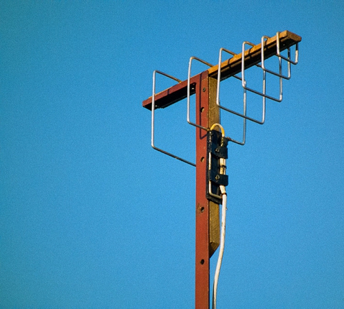
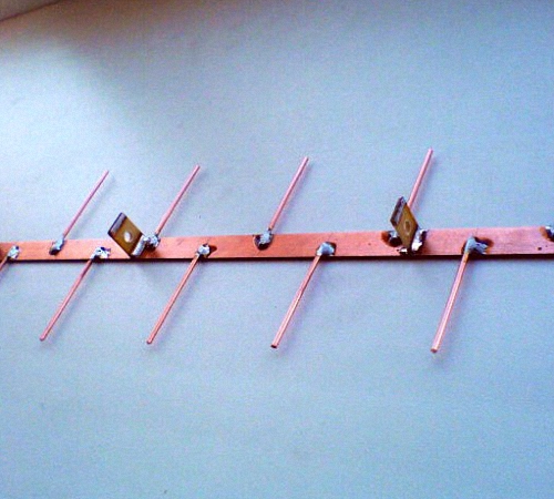
DIY UHF antenna for digital television
A log-periodic version of the antenna is called a prefabricated antenna, which is connected to the halves on a linear diopole, the interval between them varies in relation to the geometric parameters of the progression. There are configured and free lines. We suggest choosing a longer and smoother version of the antenna.
To manufacture LPA, it is necessary to have any predetermined range. The higher the progression indicators, the greater the gain of the antenna. In terms of operational and technical characteristics, this antenna option is ideal for manufacturing at home.
The main principle of its normal functioning is making correct calculations. With increasing progressive indicators, the gain increases and the directivity angle decreases. This antenna does not require an additional screen. Since it does not depend on its general characteristics.

When calculating a digital LP antenna, use the following recommendations:
- the second longest vibrator must have a reserve of frequency power;
- Next, the longest diopole is calculated;
- After this, another specified frequency range is added.
If the shortest diopole leaves lines, then it is cut off, since it is needed on the antenna only for calculations. The total length of the antenna will be about 40 cm.
The diameter of the lines on the antenna is about 7-16 mm. In this case, the interval between the axes is 40 mm. The cable is not tied to the line externally, as this will negatively affect the technical properties of the antenna.
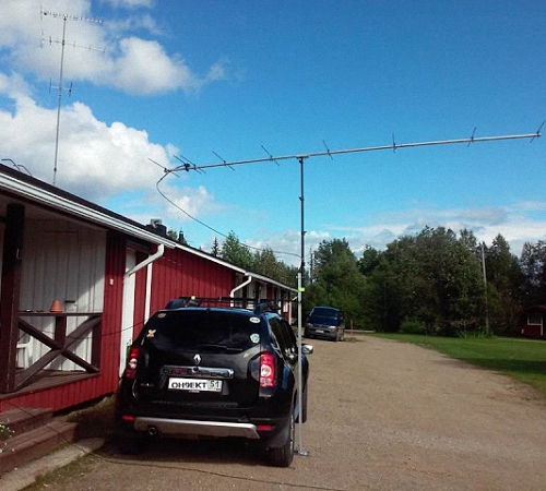
The outdoor antenna is fixed to the mast using the center of gravity. Otherwise, the antenna will constantly shake under the influence of the wind. However, the metal mast is not connected to the line in a straight line, since a dielectric mast must be provided in this place, the length of which is about 150 cm. A wooden beam, previously painted or varnished, can be used as a dielectric material.
DIY digital antenna video:
Since the advent of radio communications, the issue of using an antenna has been very relevant. In 1961, engineer Kharchenko proposed a design consisting of two rhombuses. With its help, he caught American broadcasts.
Evolution
The antenna, invented by Kharchenko, is a double square made of thick copper wire. The squares are connected to each other with open corners, and in this place they are connected. To improve directionality, a grille made of conductive material is installed at the rear.
The perimeter of each square is equal to the wavelength to which the reception is tuned. The diameter of the wire for 1-5 television channels should be about 12 cm. Because of this, for radio communications and meter range television (1-12 channels) it turns out to be very cumbersome. To facilitate the design, a gasket with three wires of a smaller cross-section was used, but it still had a lot of weight and dimensions.
The zigzag antenna created by Kharchenko received a second life when broadcasting appeared in the UHF range. Everyone remembers rhombuses, circles, triangles and other homemade figures as a TV antenna for receiving decimeter waves, which hung on many people’s balconies and outside their windows. They were one of the signs of that time.
In 2001, Professor Trevor Marshall (USA) proposed using this design in Bluetooth and WiFi networks.
This article talks about what devices are available for these purposes and how to make such an antenna with your own hands.
You can use one zigzag antenna drawing for all bands. The only differences are in size.

Antennas for TV
There is practically no meter range television, and Kharchenko’s zigzag antenna was not used to receive these channels due to its large dimensions. Therefore, this article only talks about its application for UHF and DVB-T2.
Improving UHF reception
For UHF reception, the zigzag antenna has the following dimensions:
- L1 (outer side of the square) – 141.8 mm;
- L2 (inner side of the square) – 135.6 mm;
- L3 (frame length) – 397.4 mm;
- L4 (frame width) – 198.7 mm;
- L5 (connection gap) – 8.4 mm;
- D (height of racks) – 65 mm;
- B (screen width) – 565 mm;
- H (screen length) – 565 mm;
- wire diameter – 9.6 mm;
- quantity of wire – 1166.9 mm.
It turns out to be quite broadband and does not require additional configuration. Connects using a piece of television cable. Characteristic impedance - about 50 Ohms. The antenna matches well with coaxial cable with resistance of both 50 and 75 Ohms. To improve broadband, it can be made not from wire, but from copper or aluminum strip and connected with rivets. The copper strip can be additionally soldered. The length of the strip is calculated between the rivet holes.
If you use an antenna amplifier, then the second square is not needed, you can take only one.
Improved T2 reception
Digital TV DVB-T2 is broadcast at UHF frequencies on channels 21-69 using the multiplex method. Therefore, the design for T2 needs the same dimensions as the antenna for digital television in the DCV range. However, modern TVs block it when the signal is too strong. Therefore, if the transmitter for T2 is too close, and you want to use the old frame for DVB-T2, then you may need a weaker amplifier for digital television, you will have to cut off one square or remove the screen from the back side. You can also make such a device for t2 with your own hands or use a digital TV antenna made in the form of a circle, 555 mm long. This is enough for digital TV.
Designs for the Internet, 3g and mobile communications
For mobile communications, Bluetooth, 3g and WiFi, such short waves and high frequencies are used that the entire device is about 10 cm long and is manufactured according to the same drawing for all bands. The only differences are in the sizes, which can be calculated using an online calculator. You can also use it for your mobile phone.
DIY zigzag antenna
Making an antenna yourself is not difficult. For production you need:
- single-core copper wire;
- soldering iron;
- pliers;
- ruler;
- coaxial cable with a characteristic impedance of 50 Ohms;
- conductive material for the screen (foil getinaks, DVD or CD disc, sprat can, etc.);
- a stand that provides the correct distance between the antenna and the screen, for example, a plastic bottle cap;
- glue.
The manufacturing process can be divided into several stages:
- Clean the wire from insulation;
- Using a ruler, mark the folds;
- Use pliers to bend the wire in the previously marked places. The more accurately the markings were made and the wire was bent, the better the reception will be;
- The cable connection points are tinned;
- The cable is tinned, or a plug is put on the cable, to which pieces of wire 10-15 mm long are soldered;
- The wire is soldered to the antenna;
- A stand and a screen are sequentially placed on the cable;
- The entire structure is glued, for example, with silicone.


Improved WiFi and Bluetooth reception
WiFi, like other types of wireless communications, is transmitted by radio waves. Therefore, to improve the performance of a WiFi router or other devices, you can also use this design. According to reviews, if you use a parabolic plate as a screen (alternatively, you can bend it out of a tin can), the gain reaches 31 dB. When using a homemade reflector, its curvature is selected experimentally. To do this, on the device to which the signal is transmitted, you need to install a program that shows the signal level and, changing the curvature of the screen, monitor it.
The calculation is made at a frequency of 2445 MHz.
- L1 (outer side of the square) – 30.8 mm;
- L2 (inner side of the square) – 29.6 mm;
- L3 (frame length) – 84 mm;
- L4 (frame width) – 43 mm;
- L5 (connection gap) – 1.9 mm;
- D (height of racks) – 13.6 mm;
- B (screen width) – 122 mm;
- H (screen length) – 122 mm;
- wire diameter – 2.5 mm;
- quantity of wire – 256.6mm.
Important! The more accurately the dimensions are maintained, the better the reception will be.
You can use a piece of foil getinax for printed circuit boards as a screen. For mechanical strength, the screen is soldered to the wire braid.
You can use a CD or DVD disc as a screen. The disk has a thin layer of foil on which information is recorded. In this case, you can make an antenna in a CD box.
Install the Kharchenko antenna horizontally. This is due to the polarization of the signal.
Bluetooth uses the same frequencies as WiFi. Therefore, you need a WiFi range antenna of the same size.
Connecting to a router
If the router has a connector for connecting an external antenna, then a plug is soldered to the end of the cable and inserted into the connector.
If it is not there, then to connect you need to open the modem and solder the cable to the board. The shorter the wire, the better. The power of the router is small, and cable losses are sometimes decisive.
Attention! This work can only be performed by experienced specialists. Opening the device will void the warranty.
Connecting to a laptop
Laptops have built-in WiFi cards for portability and reduced size. Therefore, there is no external antenna, and the internal one is low-power. To connect to it, you need to disassemble the laptop and know exactly where it is located. But there is an alternative option using a USB WiFi adapter with an antenna. Having cut it, you can find the central core and screen. A coaxial cable is respectively soldered to them. The ideal option would be to install directly on the adapter to reduce cable losses.
Improved 3g reception
Modern mobile Internet uses the 3g standard with a signal frequency of 2100 MHz and a wavelength of 143 mm. Therefore, the dimensions will be as follows:
- L1 (outer side of the square) – 37.1 mm;
- L2 (inner side of the square) – 35.5 mm;
- L3 (frame length) – 104 mm;
- L4 (frame width) – 52 mm;
- L5 (connection gap) – 2.2 mm;
- D (height of racks) – 17 mm;
- B (screen width) – 148 mm;
- H (screen length) – 148 mm;
- wire diameter – 2.5 mm;
- quantity of wire – 305.4 mm.
Structurally, the 3g antenna is no different from the design for WiFi.
Connecting to a 3g modem
The most effective way is to connect the cable inside the router, but to do this you need to be a specialist in the field of repairing mobile communication equipment. For everyone else, we can suggest another method.
Wireless connection
To do this, cut two pieces of copper or brass foil, 45 and 27 mm wide and long enough to wrap the modem and solder the edges. We do the same with a wide section, solder the central core of the cable to it and put it on the modem. Instead of a wide piece of foil, you can strip 15-20 cm of wire and wrap the modem tightly. A narrow piece is bent in a semicircle and soldered to the cable braid. The relative position for the best reception is selected experimentally.


Additional information. If the antenna is connected directly to the modem, without a cable, and the modem itself is connected using a USB extension cable, then losses in the cable can be avoided.
Connect to a smartphone or tablet
It is necessary to strip a piece of cable and wrap the central conductor 10-15 turns around the phone. You can also take a piece of brass or copper foil, solder the central core of the cable to it and insert it between the back cover and the case.
Improved 4g reception
Mobile Internet of the 4g standard uses a frequency of 2600 MHz with a wavelength of 115 mm. Therefore, the dimensions will be:
- L1 (outer side of the square) – 28.9 mm;
- L2 (inner side of the square) – 27.6 mm;
- L3 (frame length) – 81 mm;
- L4 (frame width) – 40.5 mm;
- L5 (connection gap) – 1.7 mm;
- D (height of racks) – 13.2 mm;
- B (screen width) – 115 mm;
- H (screen length) – 115 mm;
- wire diameter – 2 mm;
- quantity of wire – 237.9 mm.
Cell phone antenna
Mobile communications operate in two bands. You can find out which one you need on your operator’s website.
Comparative characteristics
| Options | GSM 900 | GSM 1800 |
|---|---|---|
| L1 (outer side of square) | 81.2 mm | 41.9 mm |
| L2 (inner side of square) | 77.7 mm | 40 mm |
| L3 (frame length) | 227.7 mm | 117.3 mm |
| L4 (frame width) | 113.8 mm | 58.7 mm |
| L5 (connection gap) | 4.8 mm | 2.5 mm |
| D (rack height) | 37.2 mm | 19.2 mm |
| B (screen width) | 324 mm | 167 mm |
| H (screen length) | 324 mm | 167 mm |
| Wire diameter | 5.5 mm | 2.9 mm |
| Wire length | 668.6 mm | 344.5 mm |
"Double" Bi-Quad (double biquad)
Double biquadrat is also a Kharchenko antenna. It is made with your own hands in the same way as a regular biquadrat. It differs from a regular biquadrat in that at the vertices of the squares, instead of the corners, there are additional squares. The dimensions of these squares are exactly the same as the main ones. Therefore, no additional calculation is needed; you can take the calculation for a regular biquadrat. The calculation for the Kharchenko antenna can be found in this article or use the online calculator program for the calculation. The wires at the intersection are insulated from each other.
The double biquadrat can be continued in the same way. Those who want to make it can easily calculate the length of the wire. This gives additional gain.
Rate this article:T2 digital television is actively entering our lives. Today, many homes already have antennas installed to receive such a signal. But what about those who live in the suburbs or in a rented apartment? The solution is quite simple - this is a homemade antenna for T2, which can become an inexpensive and reliable alternative to a factory-made product.
DIY TV antennas
In order to catch digital terrestrial television, first of all, you need to have a supporting new digital format TV, and then you won’t have to buy a special set-top box.
In addition, an indoor or outdoor decimeter antenna is required. You should not believe those who say that the device must be digital or something else. You can simply make a TV antenna with your own hands from scrap materials, resulting in a powerful device that will perfectly receive the signal.
Simple do-it-yourself decimeter antenna
Before preparing materials for the manufacture of the device, it is necessary to calculate its future length. To do this, you need to find out the frequency at which digital broadcasting takes place and apply a special formula: divide 7500 by the frequency in Megahertz and round the result.
A decimeter TV antenna is made from a regular 75-ohm television coaxial cable and standard connector.
After all the correct actions have been completed, the search for channels will begin. If the repeater is located in an area up to fifteen kilometers from the house, then the signal will be received well and an amplifier will not be required. If the distance is greater, then the use of an amplifier is necessary.
Do-it-yourself digital figure-of-eight antenna
In order to ensure that the signal quality is good, you can make a more complex homemade television antenna for TV.
To make it you will need to prepare:
- TV cable;
- a box;
- roulette;
- foil;
- glue;
- scotch.
The bottom of the box (for example, a shoe box) will need to be well coated with glue and completely covered with foil. In this case, it is necessary to ensure that the foil does not rise anywhere.
While the foil is sticking, you need to cut off two pieces of 50 centimeters each from the cable, and strip the ends of the insulation by carefully cutting off the outer sheath with a knife. Having bent the braid to the side at all ends, bend the segments into a circle so that they do not close completely. The distance between them should be approximately 1 centimeter.
Secure the resulting figure eight with tape to the lid of the box. In this case, you need to make sure that the stripped ends are located next to each other. The cable on the box should hold well, so there is no need to skimp on tape. The antenna frame is ready.
Now follows prepare the main cable, which will connect to the TV.

All that remains is to mount the connector for the TV. To do this, at the remaining end of the television cable you need to remove the insulation, squeeze out and cut off the braid, and remove the foil. Then, stepping back half a centimeter from the braid, remove the internal insulation of the core.
The television connector must be screwed onto the prepared cable so that the insulated core is not visible in the wide part. After this, from the edge of the connector you should retreat half a centimeter and bite off the excess part of the core, insert the second part of the connector and screw it on.
The cable and antenna are ready. Having installed the device in a convenient place, you need to point it towards the TV transmitter, connect the cable and turn on the TV. The antenna should work well and the TV should show no interference.
Homemade antenna made from cans
An antenna that will catch not one or two channels, but as many as seven or eight can be made from the simplest tin cans. To make it you will need to prepare:

First of all you should prepare the cable, removing the top layer from it at a distance of 10 centimeters from the beginning. The wiring inside the cable must be unraveled, the foil removed from under it, and one centimeter of the stripped layer cut off. You need to put a plug on the other end of the wire.
Now follows prepare the jars. Attach the cable core to the rings of one of them, and part of the unraveled wires to the other. If there are no rings, then you can screw self-tapping screws into the cans and wrap wires around them, treating the surface with a soldering iron.
After this, the jars need to be used with adhesive tape. attach to hanger. The distance between them should be 75 millimeters, the cans should be placed in one straight line.
The homemade television antenna is ready. Now you need to connect it to the TV using a plug and find a place for it where the signal will be best received.
Indoor TV antenna “Rhombus”
 This design is a diamond-shaped frame, can be manufactured quickly and easily, and receives digital television signals confidently and easily. For it you will need to prepare a copper or aluminum rod about 180 centimeters long.
There should be two diamonds. One will act as a reflector, and the second as a vibrator. The side of the frame should be approximately 14 centimeters, and the distance between them should be about 10 centimeters.
After the rhombus is made, between the two ends of the rod it is necessary to install a dielectric. Its size and shape can be arbitrary. The main thing is to ensure that the distance between the rods is about two centimeters.
Now the upper parts of the frames need to be connected, and a cable must be connected to the copper or brass petals attached to the antenna terminal.
If the repeater is located far away or the resulting device will pick up a weak signal quality, then it will be possible add amplifier. The result will be an active decimeter antenna for TV, which can be used not only in the city, but also in the country.
Of course, such devices for receiving a television signal will not have an elegant design, but with their help you can enjoy your favorite programs.