Types of hdd connectors. Basic hard drive interfaces
A hard disk is a solid-state drive, which is so called in contrast to a floppy disk, which has not been used by users for a long time. The operation of connecting a hard drive is not so complicated and in many cases the user can do everything independently, without contacting computer specialists.
In what cases do you have to connect hard drives?
- When upgrading, you replace the old drive with a more powerful and larger one.
- To expand disk memory. For example, to place computer games and some applications on a separate hard drive.
- During repair - replacing a failed drive with a functional one.
- To read large amounts of previously recorded information.
Basic provisions
If in system unit with an IDE interface there is more than one hard drive, then one of them on the bus is designated as the main one, and the second as the auxiliary one. The first one is called Master, and the other one is called Slave. Such a division is required so that when loading the operating system after turning on, the computer knows exactly which disk is the boot one.
In all cases, you can set the boot sequence from drives using the BIOS settings. And in IDE this is done by installing jumpers on the disk enclosures according to the diagram shown on the enclosure.
By type of interface, hard drives differ between IDE – the old model and SATA – in all new computers. If you have an older model of system unit and you are going to connect a new hard drive with a SATA interface, you will need to purchase a special adapter.
Junk
It happens that you pick up this old thing and can’t figure out what to connect and where. Old interface IDE (1986) is attached to a parallel cable. Usually there are either 2 or 4 connectors on the motherboard. Always an even number, because the Master/Slave rule works. Settings can be specified using jumpers (example):
- Master – the presence of a jumper between the leftmost contacts (7 and 8) of the control connector.
- Slave – absence of any jumpers.
The specified configuration may vary depending on the manufacturer, as well as the set valid functions, specified by the connector. The IDE interface made it possible to conveniently connect a hard drive and a CD drive to the computer at the same time. This was enough for most users. The disadvantage of the parallel interface was the low transfer speed. In another way, IDE is referred to among professionals as parallel ATA or ATA-1. The transfer speed of such devices does not exceed 133 Mbit/s (for ATA-7). With the introduction of the serial SATA interface in 2003, the aging information transfer protocol began to be called parallel PATA.
The name ATA-1 was assigned to the IDE interface in 1994 when it was recognized by the ANSI organization. Formally, it was an extension of the 16-bit ISA buses(predecessor of PCI). It is curious that in modern world There is a trend of using video card interfaces to create ports for connecting hard drives. This was followed by accelerated ATA-2 and packet ATAPI. IDE interface not officially supported since December 2013. Connecting such a hard drive to a new motherboard is only possible with an expansion card.

Using such devices, you can perform the exact opposite function: install previous generation hard drives on new motherboards. So, for example, on the old A7N8X-X there are only two IDE port, but there are 5 PCI 2.2 slots for expansion cards. Universal adapter just right for this occasion. And you can install a modern hard drive up to SATA3, but its operating speed will, of course, be several times lower than the maximum.

Hard drives for standard IDE interfaces are probably already mostly out of order. And there are not so many of them left in the world. It remains to add to this that the configuration of ATA devices can be changed using jumpers, and the explanatory drawing is located directly on the device body. Unscrupulous suppliers sometimes keep jumpers for themselves, and not every configuration in this case can be carried out by the user. There are usually not enough jumpers.
Today there is a new trend: for some time replaced by cards PCI Express Traditional PCI is making a comeback on motherboards. This means that “old stuff” can now be connected to a modern system unit using an adapter.

SATA drives
Experts generally distinguish three generations of SATA. The gradation is based on the speed of information transfer:
- SATA – 1.5 Gbit/s.
- SATA2 – 3 Gbit/s.
- SATA3 – 6 Gbit/s.
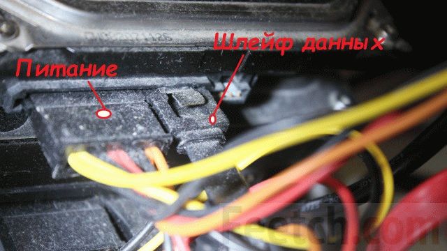
A standard SATA drive has two connectors, one of which is used for power supply, and the second serves as a data transfer cable. It is not recommended to swap hard drives by connecting them to different SATA ports. The plugs have keys that prevent the connector from being connected incorrectly.
Sometimes the hard drive can contain useful information that any advanced user can understand. But sometimes the designation tends to be so ornate that only a true professional can comprehend it. As, for example, in this case.

There is information about the brand, serial number, technical data and even measures of disk capacity. But its interface remains unknown. This is important when choosing hardware for a computer with disabilities. If the disk had a SATA3 interface, then it is useless to install one in an old system unit. There are many others similar examples. Let's say in advance that this drive has a SATA 2.6 interface. Consequently, its information exchange rate limit is 3 Mbit/s.
If information about the HDD interface type is available
How to distinguish? First, you can look at the body. Here is an image of an old disk that supports two speeds, therefore, it is a SATA2 device.

When removed from the system unit, it was equipped with a jumper that reduced the speed.

The jumper was immediately removed, therefore, the device will now function twice as fast. On SATA 2.0 bus motherboard GA-H61M-D2-B3.
This once again suggests that it is not enough to buy a system unit; you also need to study its entire device in general and hard drives in particular. The drives inside were paired using a special hanging frame.

This achieves better maintainability of the structure. Both hard drives were quickly removed from the case. An alternative is to install it in a bay, where the housing is secured with screws on both sides, and two side covers must be removed for removal. Which is not very convenient, considering that each of them usually jams. It is rare to find system unit cases where the sidewalls are removed using simple methods.
If HDD interface data is missing
Sometimes the hard drive may not have data transfer speed information. In this case, you can, of course, stock up on AIDA, but it’s even easier to look up the information on the Internet. The brand of the drive is determined by the price list or the appearance of the case.

Let's say we have WD5000AAJS in our hands. Only one thing is known - at lunchtime he will be a hundred years old. Therefore, you need to familiarize yourself with historical information in the Internet. Since models are constantly updated, you need to enter the code followed by a dash - 00YFA0. The search engine quickly provided an answer, and now there is every reason to claim that the channel bandwidth is 3 Gbit/s (SATA 2.5 generation).

We have already discussed above how to connect such equipment to an outdated motherboard that does not have a SATA interface. So let's move on to new products.
Connecting SATA to exSATA bus
When engineers approached the problem of increasing SATA speeds to 12 Gbit/s and higher, it turned out that this was not economically viable. Energy efficiency drops sharply while prices rise. Someone noticed that the tire graphic cards PCI Express works without problems at high speeds, and then it was decided to make some kind of hybrid between it and the now obsolete SATA. To do this, the connector was divided into two parts:
- Specific. Small port on the side.
- Standard. Two ports for SATA0 connection.

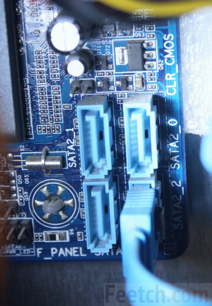
The figure shows a dual exSATA port. This can include 4 hard drives with a SATA interface, or 2 exSATA, or 1 exSATA and 2 SATA. Below is an example of connecting two SATA drives to one exSATA port.
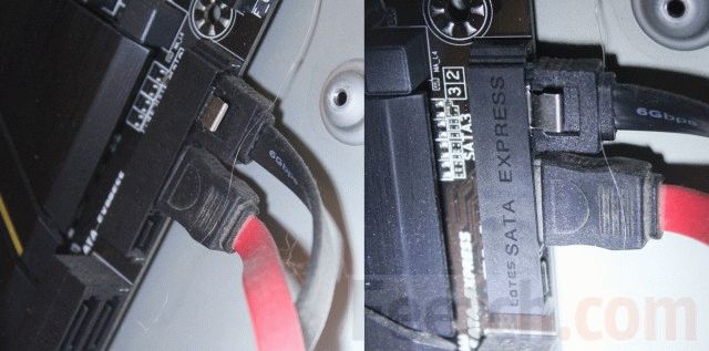
Because of their large sizes A plug covering three exSATA slots at once is called a hub among professionals. You need to start by checking the BIOS. It turned out that some motherboards can turn off SATA support, completely switching to Express, which supports speeds of up to 16 Gbps.

At the same time, you can look at the BIOS capabilities regarding RAID arrays. Let us remember that in the latter case, several hard drives can duplicate their information for reliability, or turn on alternately, which significantly increases the speed of operation. The size of the article does not allow us to speak in more detail on this topic.
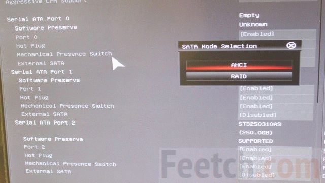
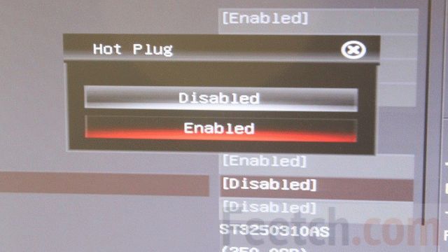
The selected AHCI mode is the default mode for most systems. It provides maximum compatibility with older equipment in a completely transparent manner for the user. To safely hot-plug drives, it is recommended to set the appropriate option in the BIOS settings.
When installing a new operating system, the sequence for connecting bootable media is specified. The hard drive is not put in first place. Instead, leadership is given to a flash drive or DVD drive.
Before connecting

How to connect an IDE hard drive
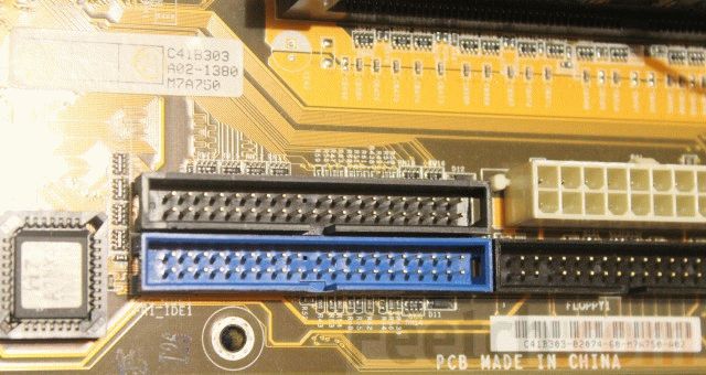
On the motherboard, the IDE connector is visible from afar. You can recognize it by its characteristic slot with many contacts and a key located approximately in the center of the block.
A splitter cable is usually hung on each port, so that a master and a servant are on the channel at the same time.

Before connecting a drive, you need to correctly configure the jumpers on its case - Slave or Master. There will definitely be a diagram on the case on how to do this.

For discs from different manufacturers the order in which the jumpers are inserted will be unique (they seem to be competing in this). The disk must be a bus master, otherwise the operating system cannot be started from it (No IDE Master detected). Therefore, it is necessary to set the slave jumper on the CD drive.

After setting the jumpers, insert the hard drive into a suitable cage and secure it with four screws on both sides. Connect the single data cable connector to the corresponding header on the motherboard. Connect the power cables. The order doesn't matter here.
Now you can close the system unit covers and connect the computer. The system itself should detect new connections and configure everything. The user will only have to confirm operations in the Add New Equipment Wizard.
If the system is confused about where the Master is and where the Slave is, then it is necessary to make assignments in the BIOS. Immediately after turning on the power, press the F2 or Del key repeatedly (in different ways) to open BIOS installation. Find the interface for describing the order of boot devices, set the parameters. The first is the CD drive from which the system is installed. Save the settings using the F10 key. After this, the operating system will begin loading.
How to connect a SATA hard drive to an old motherboard
To connect a SATA hard drive, use a PCI bus adapter. It may have one or another number of ports; accordingly, several hard drives are installed.

Insert the card into the slot, connect the hard drive, place it in the bay and secure it with screws on both sides - two or four screws in total. It is advisable to choose the location of the modules inside the system unit in such a way that, if possible, there is enough free space between them to ensure ventilation. Otherwise, if the computer overheats, it will automatically turn off.
Now connect the power cable to the hard drive. If the power supply is an old model for IDE, you will need an adapter to connect SATA. Now you can connect the data cable to the hard drive. After the system boots, you should install the driver from the included DVD, and the new drive will become visible through Explorer.

Sometimes there is no other drive other than SATA. And then you need to install Windows again via a PCI adapter. The bootloader will not see the drive, but will give you the opportunity to find it manually. This is where you will need to find it on DVD required driver for the current operating system. The installer will then notice the disk and you can create partitions for the new operating system. This is absolutely accurate, because the authors installed the “seven” in this way on an old system unit.
The article is dedicated to my friend,
which I bought for my home computer
hard Seagate Cheetah UWSCSI.
Today there is great amount various technologies and hard drive interfaces. The number of foreign and incomprehensible words clogging the great and mighty language of computer equipment sellers is growing all the time, and when you come to the store for a new hard drive, you can hear so many things. For example: IDE, ATA, Serial ATA, SCSI, SCSI II, Wide SCSI II, Ultra SCSI II, Ultra Wide SCSI II, Ultra2 SCSI, Ultra160 SCSI, Fiber Channel, IEEE 1394, FireWire, iLink, USB, RAID, 5400rpm, 7200rpm , 10,000rpm, 15,000rpm... So how? Are your ears already applauding? So this article should help you figure out which device that the seller will try to sell you is really worth buying. I hope you make the right decision.
And take note. This article is not just for great, super-duper computer geeks. And not even for them at all. They already know everything. This article is intended for the average hard drive buyer who has little understanding of all of the above terms. Let's say you're building a new computer or upgrading an old one. You've thought about a SCSI hard drive, but you know very little about this interface, and you've also heard something, perhaps even good, about IEEE 1394, but you have absolutely no idea what it's used with. Then you've come to the right place.
Interfaces.
First of all, you need to think about the disk with which interface you will buy. Firmly settled on an IDE? What about SCSI, IEEE 1394 or USB? Depending on the interface is tough drives can differ in speed characteristics, cost, cable length, flexibility and reliability, and who knows what else. So we'll start with interfaces.
IDE/ATA
IDE (Integrated Drive Electronics) is the name of a type of hard drive that has an ATA (AT Attachment) interface. Cheap IDE electronics combined with parallel ATA transfers produce hard drives that will take you around the world. However, do not forget that ATA is not intended for external connections, and does not like cables longer than 60cm. That is, you can buy such ATA cables, but I don’t recommend using them.
One ATA channel can support up to two drives, the first is the master and the secondary is the slave. Very often, if not almost always, people put on one channel HDD as a master and another, slower device, such as a CD-ROM, as a slave. But since the IDE can only access one device on a channel at a time, this reduces the performance of the system as a whole. So it’s better not to have slave devices at all. Especially. That now all motherboards have two integrated IDE channels, and some (like my favorite ABIT BX-133 RAID) have four. Simply connect the hard drive as master to the first channel, and the DVD or CD-ROM as master to the second channel.
There are three main standards on the market today IDE drives: ATA/33, ATA/66 and ATA/100. In this case, the number shows the maximum throughput in megabytes per second. Just remember that ATA/66 and ATA/100 require a special ATA/66/100 80-pin cable, and with a standard 40-pin cable your ATA/66/100 drive will work like an ATA/33. As a rule, such a cable comes with all motherboards that support ATA/66/100. These three standards are collectively called UDMA. Although this is incorrect, you will often hear UDMA, ATA and IDE used interchangeably.
All IDE drives must work with all ATA variants. An ATA/100 drive should work just fine with an ATA/33 controller, and an ATA/33 drive should work just as well with an ATA/100 controller. But, it is clear that the hard drive will operate at the speed of the slowest component. In both of these cases, it will be ATA/33 speed, that is, the maximum throughput will be 33Mb/sec. Sometimes you can come across some incompatibilities, such as when a particular drive does not want to work with a particular cable, or two drives from different manufacturers do not want to coexist on the same controller channel. Well, electronics are a complicated thing. To make sure of this, just disassemble the hard drive and see where all these gigabytes are located inside. But it’s better to do this with a “dead” hard drive, and not with the one on which a collection of your favorite pictures and texts about Winnie the Pooh is stored.
In fact, the difference in performance between ATA/33, 66 and 100 is not that great, since we are talking about peak throughput, which is rarely achieved in real work. There are no ATA/100 drives capable of transferring data even at 66MB/sec, and very few that do. That allows transfer of 33Mb/sec. Only the hard disk cache can take advantage of the increased throughput. But for this, the cache size must be large enough. And most IDE drives have only 512KB of cache memory, and only a few, the most expensive ones, can boast of a 2 or even 4 MB cache.
So the main disadvantage of the IDE is still its low speed. Certainly. Modern IDE drives have caught up speed characteristics old models of SCSI drives, but they still can’t compare with new SCSI hard drives. You can buy a fairly fast IDE drive with a rotation speed of 7200 revolutions per minute (rpm), but you can also buy a SCSI drive with a speed of 15,000 rpm, which will be much faster. Also, the time between failures, as stated by manufacturers, is much shorter for IDE drives than for SCSI drives. It may just be marketing, but there is a widespread belief that SCSI devices are more reliable than IDE devices.
However, even discs with a spindle speed of 7200 rpm are quite expensive. Most models on our market have a rotation speed of 5400rpm. Such drives cost $30-40 less and produce less noise, but they have less performance. Although for home use, this is what you need.
The future of the ATA is likely. It lies on the path to the transition to the Serial ATA standard. Serial ATA will have a cable with just two pins (one receive, one transmit), and must provide IDE throughput up to 1.5 Gbit/s, and possibly more. This doubles the bandwidth of the ATA/100, which has 40 times more pins. The only one negative side Serial ATA is that there can only be one device on one channel, but if you have a controller with multiple channels this is not a problem.
Advantages- Good performance for little money
- Widespread, and therefore compatible with most existing equipment.
- Not the fastest wheels
- Strict limitation on cable length
- Only internal
SCSI
SCSI has long been standard interface for workstations and servers. And although SCSI is significantly more expensive than IDE, for this money we get much greater bandwidth, support more devices on one channel, much longer cable lengths (up to 12 meters), support for external devices and multitasking. Quite a lot, isn't it?
A regular (sometimes called “narrow”) SCSI bus can carry up to 8 devices, and a wide bus can carry up to 16. The SCSI controller itself occupies one address, and leaves the remaining 15 for connected devices (accordingly, on the narrow bus there are 7 addresses left for devices ). Higher SCSI addresses have higher priority. This makes SCSI installation a bit of a chore. It is usually better to give higher priority to slow devices such as CD-ROMs rather than hard drives.
There are many different SCSI options. We have already written about them, and I recommend the article “SCSI Interfaces” to anyone who wants to study this issue in detail. Among the devices currently available on the market are Ultra, Ultra2 and Ultra160 SCSI. Ultra SCSI allows transfer of 20Mb/s and has 8 addresses. The wide version of Ultra SCSI doubles the throughput, that is, up to 40 MB/sec. Ultra2 SCSI, also known as LVD (Low Voltage Differential) SCSI, has a throughput of 40 Mb/s, and, accordingly, its wide version gives us 80 Mb/s. Ultra160 SCSI continues the tradition of doubling the throughput, but comes only in the wide version, which gives us 16 devices per channel and 160Mb/s.
SCSI devices, as a rule, have compatibility, as they say, from top to bottom. True, no one guarantees this, but in most cases, let's say for example, a SCSI-2 device will feel great on an Ultra2Wide SCSI controller. However, it happens that if there are fast and slow devices on the same bus, both begin to work at the maximum speed of the slow one. But in fact, how different SCSI devices suspended nearby will behave depends mainly on the controller.
With SCSI, problems often arise regarding installation and first configuration, especially for those who are doing this for the first time. All these terminators and identifiers can cause a serious headache. At the same time, all these problems are more than compensated by the reliability of this interface. And the appearance of active terminators (they have nothing to do with robots from the future) has significantly simplified the installation of SCSI devices. So rejoice, it was worse before.
The main advantage, the main strength of SCSI is expressed by the capacious foreign word high-end, that is, the fastest, most capacious hard drives have a SCSI interface. The Seagate Cheetah with 15,000 spindle rpm in the IDE version has never been produced and is unlikely to be. Well, the ability to support up to 15 devices on one channel indicates excellent scalability, which is also extremely important for certain purposes.
The world of SCSI is so vast that this is not even a topic for one article, so before putting a bullet in this section I’ll just say a few more words about the future.
And the future of SCSI is already planned out like clockwork. The first Ultra320 devices are already appearing, and the next step will be the Ultra640. The SCSI standard itself was originally intended to be scalable, and has become so scalable that it is unlikely that anything can compare with it in this regard.
Advantages- Great productivity
- Large volumes
- Possibility of connecting both internal and external devices
- Expensive
- There may be problems during installation
Fiber Channel
Fiber channel is an interface that is fundamentally different from SCSI and IDE. It's actually closer to Ethernet and InfiniBand, if that tells you anything. And if not, then understand the following: this interface is intended not only for connecting hard drives and all other peripherals to the system, but primarily for organizing networks, combining remote friend from each other hard drive arrays, and other operations requiring high throughput in combination with long distances. Fiber channel is often used to connect SCSI RAID arrays to a workgroup network or server.
Existing technologies allow Fiber channel throughput of 100 Mbit/s, and the theoretical limit of this technology lies somewhere around 1.06 Gbit/s. At the same time, a number of companies are already developing devices with a throughput of up to 2.12 Gbit/s, but this is the next generation of the Fiber channel interface. There are also solutions on today's market where a number of Fiber channels are used simultaneously to achieve super-high throughput.
Unlike SCSI, Fiber channel has much more flexibility. If SCSI is limited to only 12 meters, then Fiber channel allows connections up to 10 km long when using an optical cable and somewhat less when using relatively inexpensive copper connections, although relatively inexpensive ;-).
Advantages- Very good scalability
- Very long distances connections (up to 10 km)
- A network of many workstations can work with one RAID array
- Expensive
- Very expensive
- The better, the more expensive
IEEE 1394
IEEE 1394, aka FireWire (as Apple called it), aka iLink (as Sony called it), is really becoming a standard for transmitting digital video, but can also be used to connect hard drives, scanners, network equipment, digital cameras, and everything that requires good bandwidth. Currently, FireWire remains a fairly expensive solution (according to at least, for the average user), but the standard is increasingly penetrating all areas of computer peripherals and is constantly becoming cheaper.
FireWire is capable of supporting up to 63 devices on a single 400Mbps channel. And IEEE 1394b, the first attempt at a major overhaul of FireWire, will support throughput of 800 Mbps per channel. FireWire provides better performance, but external devices with this interface require separate external source nutrition.
The first FireWire hard drives are already starting to appear, and models that use an IDE/FireWire translator have been around for quite some time. But this interface is already widely used for video cameras, scanners and printers. High-performance local networks can also be built on FireWire. Many Apple computer models have one or two FireWire ports, but on PCs this standard has not yet received such recognition.
The best feature of FireWire is its hot pluggability. That is, you can connect and disconnect FireWire devices without turning off the computer. But if such a device is a hard drive, then the operating system must be able to mount new hard drives on the fly.
The future of IEEE 1394 looks quite optimistic, given the youth of this standard, and the almost ready specification 1394b, which allows doubling the throughput. And the recognition of this standard is a matter of the near future; its popularity is growing every day, and prices are correspondingly falling.
Advantages- Hot plugging
- High throughput
- No prioritization of devices
- Hard drive controllers are still very expensive
USB
USB 1 (Universal Serial Bus) is a standard that has become extremely widespread over the past few years. It's hard to find a computer that doesn't have USB support (unless it's an old Pentium100). This interface has two speed modes. The first - “high-speed” - provides a throughput of 12 Mbit/s and a connecting cable length of up to 5 meters. The second is low-speed - bandwidth 1.5 Mbit/s and cable length up to 3 meters. It is clear that this standard is of little use for hard drives due to its slowness, but for all kinds of devices Reserve copy, CD-R, scanners, network devices and input devices are quite suitable.
One USB channel can contain up to 127 devices, for which devices that pass the signal through themselves or USB hubs can be used. USB has what is called a master controller, so any signal sent from, say, a USB hard drive to a USB CDR must pass through the controller and then go to the desired device. This greatly reduces throughput when using multiple USB devices. Besides, USB devices cannot be shared (on a network, for example), although two computers can be connected to each other USB network via USB bridge.
But, with all its disadvantages, USB allows “hot” connection. True, the operating system will still require you to provide a driver for a new device, but you will not have to restart the computer. Although this is debatable. For example, I recently came across LAN card USB (a convenient means for connecting a sealed computer to the network), so I connected it “hot”, and after installing the drivers, Windows offered to reboot. So, as they say, even the morgue doesn’t give you 100%.
Well, everything is already known about the future of USB (at least the near future). This future will be USB 2, and not someday, but around the beginning of next year. USB 2 will raise the bandwidth bar from 12 to 480 Mbps. Then it will be possible to seriously think about a hard drive with a USB 2 interface. In the meantime, there is debate on the Internet whether USB 2 will be replaced by FireWire or whether both standards will find themselves in different areas of computer peripherals.
Advantages- Widespread
- Low cost
- Hot plugging
- Low efficiency for communication between devices
- Low speed (USB 2 will fix this)
- Short length of connecting cables
So choose what?
In fact, the choice is already determined by your goal. If you are building a home computer for gaming or office work, then an IDE drive will give you the best price/performance combination. USB works well for an external CDR or tape drive for backup (as long as you don't copy too much). Like, cheap and cheerful, but you can carry it from place to place as much as you like. If you need a fast external drive to connect to a laptop, or for regular transfer between several computers, and the main requirement besides mobility is performance, then IEEE 1394 is your choice. If we are talking about equipping a serious workstation or servers where reliability and performance are critical, then the best choice is SCSI, especially in the form of RAID, although it costs a lot. Well, if you are forming a cluster of automated workstations that require high-speed access to a large array of data, then the Fiber channel will provide you with speed; the remoteness of the workstations from the array of information practically does not matter. Another possibility is to create a Gigabit Ethernet network, and for the server, as a rule, they choose a RAID SCSI solution, or, for non-critical servers, IDE RAID.
So what is RAID?
RAID stands for Redundant Array of Inexpensive Disks, or in Russian - Redundant Array of Inexpensive Disks (yeah, I saw these inexpensive ones, my entire computer costs less than the hard drives in those RAIDs). RAID has two main goals, to improve speed and/or reliability. There are quite a few types of RAID, but the main ones are RAID 0, 1 and 0+1. RAID 0 allows you to combine the capacity of two disks into a single unit, so that the operating system will see them and use them as one physical disk. RAID 1 allows you to create a “mirror”, that is, information is written immediately to both the first and second disk, and if the first, main hard drive “dies,” then all the data on the second will be safe and sound. Well, and finally, RAID 0+1 simultaneously uses the two modes described above (do not forget that this requires at least four hard drives, two are merged into the array, and two are used for the “mirror”). There are also other RAID options to improve the reliability of information storage, such as parity, to check data integrity.
What about the size?
Are you having trouble figuring out how much space you'll need? 10GB is the minimum volume that can be purchased today. Although there are still smaller hard drives lying around, but by the time you finish reading this article, by the time you are ready to buy something, they will no longer be on sale. If you are fond of collecting MP3 music, downloading a lot of video clips from the Internet (then you have a dedicated line :-) and you will need at least 20 or 30GB. Well, if you want to start creating animation, video processing, etc., then 50-100GB will be just right.
Everything you read should not be taken to heart. Shouts like “I have a small hard drive, and the girls in class laugh at me” are also not necessary. Time will pass, the hard drive will grow, and everything will be fine.
Write to me at [email protected], just don’t ask for free hard drives. I still won't give it :-).
Good day! In the last post, we looked at the hard drive structure in detail, but I didn’t specifically say anything about interfaces - that is, the ways of interaction between the hard drive and other computer devices, or more specifically, the ways of interaction (connection) between the hard drive and the motherboard of the PC.
Why didn't you say so? But because this topic is worthy of no less than an entire post. So now we will analyze in detail the most popular interfaces today. I’ll immediately make a reservation that the entry or post (whichever is more convenient for you) this time will have an impressive size, but unfortunately there’s no way to do without it, because if you write briefly, it won’t be entirely clear.
Quick navigation
PC hard drive interface concept
First, let's define the concept of “interface”. In simple terms (and that is what I will express myself as much as possible, since the blog is on ordinary people designed for people like you and me), interface is the way devices interact with each other and not only devices. For example, many of you must have heard about the so-called “friendly” interface of a program. What does it mean? This means that the interaction between a person and a program is easier and does not require the user to great effort, compared to the “not friendly” interface. In our case, the interface is simply a way of interaction between the hard drive and the computer’s motherboard. It is a set of special lines and a special protocol (a set of data transfer rules). That is, purely physically - a cable (cable, wire), on both sides of which there are inputs, and on the hard drive and motherboard there are special ports (places where the cable is connected). Thus, the concept of interface includes a connecting cable and ports located on the devices it connects.
Types of interaction between screws and the computer’s motherboard (types of interfaces)
Well, first in line we will have the most “ancient” (80s) of all, you can no longer find it in modern HDDs, this is the IDE interface (aka ATA, PATA).
IDE
IDE - translated from English as “Integrated Drive Electronics”, which literally means “built-in controller”. It was only later that IDE began to be called an interface for data transfer, due to the fact that the controller (located in the device, mainly in hard drives and optical drives) and had to be connected with something. It (IDE) is also called ATA (Advanced Technology Attachment), it turns out something like “Advanced Connection Technology”. The fact is that ATA is a parallel data transfer interface, for which soon (literally immediately after the release of SATA, about which we'll talk just below) it was renamed PATA (Parallel ATA).
What can I say, although the IDE was very slow (the data transfer bandwidth ranged from 100 to 133 megabytes per second in different versions of the IDE - and even then purely theoretically, in practice it was much less), but it allowed you to connect two devices to the motherboard at once , using one loop.
Moreover, in the case of connecting 2 devices at once, the line capacity was divided in half. But this is far from the only drawback of the IDE. The wire itself, as can be seen from the figure, is quite wide and, when connected, will take up the lion's share of the free space in the system unit, which will negatively affect the cooling of the entire system. In general, IDE is already outdated morally and physically; for this reason, the IDE connector can no longer be found on many modern motherboards, although until recently they were still installed (in the amount of 1 piece) on budget motherboards and on some boards in the mid-price segment.
SATA
The next interface, no less popular than IDE in its time, is SATA (Serial ATA), characteristic feature which is serial data transmission. It is worth noting that at the time of writing this post it is the most widespread for use in computers.
There are three main variants (revisions) of SATA, differing from each other in throughput: rev. 1 (SATA I) - 150 Mb/s, rev. 2 (SATA II) - 300 Mb/s, rev. three (SATA III) - 600 Mb/s. But this is only in theory. In practice, the write/read speed of screws generally does not exceed 100-150 MB/s, and the remaining speed is not yet in demand and only affects the speed of interaction between the controller and the HDD cache memory (increases the disk access speed).
Among the innovations, I would like to note - backward compatibility of all versions of SATA (a disk with a SATA rev. 2 connector can be connected to a motherboard with a SATA rev. three connector, etc.), improved appearance and ease of connecting/disconnecting the cable, increased compared to IDE cable length (1 meter maximum, versus 46 cm on the IDE interface), support for the NCQ function starting from the first revision. I hasten to please owners of old devices that do not support SATA - there are adapters from PATA to SATA, this is a real way out of the situation, allowing you to avoid wasting money on buying a new motherboard or new hard disk.
Also, unlike PATA, the SATA interface provides for “hot-swappable” hard drives, which means that when the computer’s system unit is powered on, you can attach/detach hard drives. Only to implement it you will need to delve a little into the BIOS settings and enable AHCI mode.
eSATA (External SATA)
The next one on the list is eSATA (External SATA) - was created in 2004, the word “external” indicates that it is used for connecting external hard disks. Supports hot-swap disks. The length of the interface cable is increased compared to SATA - maximum length is currently as much as two meters. eSATA is not physically compatible with SATA, but has the same bandwidth.
But eSATA is far from the only way to connect external devices to a computer. For example, FireWire is a high-speed serial interface for connecting external devices, including HDD.
Supports hot-swappable screws. In terms of bandwidth it is comparable to USB 2.0, and with the advent of USB 3.0 it even loses in speed. However, it still has the advantage that FireWire can provide isochronous data transmission, which facilitates its use in digital video, as it makes it possible to transmit data in real time. Sure, FireWire is popular, but not as popular as example USB or eSATA. It is used quite rarely to connect screws; in most cases, various multimedia devices are connected using FireWire.
USB (Universal Serial Bus)
USB (Universal Serial Bus) is perhaps the most common interface used to connect external hard drives, flash drives and solid-state drives (SSD). As in the previous case, there is support for “hot swap”; the maximum length of the connecting cable is quite large - up to 5 meters in case USB usage 2.0, and up to three meters - if USB 3.0 is used. It is probably possible to make the cable longer, but in this case the stable operation of the devices will be in question.
Transmission speed USB data 2.0 is about 40 Mb/s, which is generally a low figure. Yes, of course, for an ordinary daily work with files, a channel bandwidth of 40 Mb/s is enough, but as soon as we start talking about working with large files, you will inevitably start looking towards something faster. But it turns out there is a way out, and its name is USB 3.0, the bandwidth of which, compared to its predecessor, has increased 10 times and is about 380 Mb/s, that is, almost the same as SATA II, even a little more.
There are two types of contacts USB cable, these are type "A" and type "B", located at opposite ends of the cable. Type “A” is the controller (motherboard), type “B” is the connected device.
USB 3.0 (Type "A") is compatible with USB 2.0 (Type "A"). Types "B" are not compatible with each other, as can be seen from the figure.
Thunderbolt (Light Peak)
Thunderbolt (Light Peak). In 2010, Intel demonstrated the first computer with this interface, and a little later, the no less famous company Apple joined Intel in supporting Thunderbolt. Thunderbolt is pretty cool (how could it be otherwise, Apple knows what is worth investing in), is it worth talking about its support for such features as: the notorious “hot swap”, immediate connection to several devices at once, truly “huge” data transfer speed (20 times faster than USB 2.0).
The maximum cable length is only three meters (apparently more is not necessary). However, despite all the listed advantages, Thunderbolt is not yet “massive” and is used mainly in expensive devices.
Go ahead. Next up we have a couple of interfaces that are very similar to each other - SAS and SCSI. Their similarity lies in the fact that they are both used primarily in servers where high performance and the shortest possible access time are required. hard drive. But there is also a flip side to the coin - all the advantages of these interfaces are offset by the price of devices that support them. Hard drives that support SCSI or SAS are much more expensive.
SCSI (Small Computer System Interface)
SCSI (Small Computer System Interface) is a parallel interface for connecting various external devices (not just hard drives).
It was developed and standardized even somewhat earlier than the first version of SATA. The latest versions of SCSI have hot-swap support.
SAS (Serial Attached SCSI)
SAS (Serial Attached SCSI), which replaced SCSI, was supposed to solve a number of the latter's shortcomings. And I must say - he succeeded. The fact is that, due to its “parallelism,” SCSI used a common bus, so only one of the devices could work with the controller at once; SAS does not have this drawback.
In addition, it is backward compatible with SATA, which is undoubtedly a big plus. Unfortunately, the price of screws with a SAS interface is close to the cost of SCSI hard drives, but there is no way to get rid of this; you have to pay for speed.
NAS (Network Attached Storage)
If you are not tired yet, I suggest you consider another cool way HDD connections- NAS (Network Attached Storage). Currently, network-attached storage systems (NAS) are very popular. Essentially, this is a separate computer, a kind of mini-server, responsible for storing data. It connects to another PC via network cable and is controlled from another computer through a regular browser. All this is necessary in cases where large disk space is required, which is used by several people at once (in the family, at work). Data from the network storage is transferred to the user’s personal accounts either via a regular cable (Ethernet), or by Wi-Fi assistance. In my opinion, a very convenient thing.
I hope you liked the material, I suggest you bookmark the blog so you don’t miss anything and we’ll meet you in the next posts on the site.
Hello! I received a very interesting question by email.
My reader encountered an installation problem old hard drive with IDE connector to a new motherboard, where only SATA controllers
. And the problem is not so much the need to use the old hard drive, but to gain access to the information that was stored on the old hard drive.
Many users have the need to connect an old hard drive to a computer, so I offer my solution.
This is what SATA/IDE hard drive connectors look like.
Of course, these connectors are not compatible with each other. The IDE connector is connected to the motherboard with a wide flat cable, and the SATA connector is connected to a thin SATA cable.

The fact is that motherboard manufacturers try to save on every little thing. Why install outdated connectors on the board if almost no one uses them anymore? Connectors will only take up extra space and increase the cost of the motherboard.
In addition, I suggest you take a look at this article - the cheapest way to connect an IDE device, which will also help you solve the issue.
We are looking for a solution!
So we can do like this NOT professionals. We install the old IDE hard drive in another computer with IDE connectors, copy all the necessary information from it to a flash drive or external hard disk, then copy all the information to the new computer. Great, the information is saved, but what should we do with the old disk? Just put it on the shelf and forget about it - this is not our method.
We'll go the other way, so for IDE connections hard drive we will need a PCI - SATA/IDE controller.
Controllers may differ from each other by manufacturer, number of connectors, and may be implemented on different chips, but these differences do not affect the principle of working with them.
This is what this miracle of technology looks like. And here is a link to a similar option for ordering from China - http://aliexpress.com/pci-ide-sata (note that the controller in the link has a pci express-x1 connector)

The cost of such a controller is about 400-500 rubles. And it works out its cost 100%, since in return we get the opportunity to install both old HDDs on new motherboards and new hard drives on old motherboards.
This controller has several SATA connectors and one IDE controller on board. Do not forget that we can connect 2 devices to one IDE controller, which is why the IDE cables have connectors for connecting 2 devices at once.
All we need to do is connect the PCI-SATA/IDE controller to the motherboard. To do this we just need to plug it into the connector PCI motherboard and secure with a bolt.

After connecting the connector, all we have to do is secure the hard drive inside the case and connect two wires to it (data cable and power).
Thus we get the following connection diagram.

- connect the controller to the motherboard;
- connect the IDE cable to the controller;
- connect the cable to the hard drive;
- connect power to the disk;
Please note that the power connectors for IDE and SATA hard drives are also different. Usually, the computer power supply has plenty of both connectors, but sometimes to connect SATA hard drives you have to use a molex (PATA) to SATA adapter.

If you don't have enough molex power connectors, use special power strips.

After we have figured out the connection, all we have to do is turn on the computer and make sure that the hard drive is detected in the system. To do this, just go to “My Computer” and look at your local drives. In addition to the existing ones, should local disks of the new hard drive be added?
I would also like to draw your attention to the fact that, although the kit includes a disk with drivers given the controller does not need to install them. The system itself will find the necessary drivers.
Finally, I’ll add one more argument in favor of PCI-SATA/IDE controller. You can safely install an operating system on a hard drive connected through such a controller, which I have proven many times.
This is how this very useful device can make our lives easier.
As always, we leave our impressions, comments, and suggestions for the article in the comments below. I try to answer each of them.
See you in the next lesson, where I will tell you, how to test a hard drive for bad blocks.
PS. I hope many readers have noticed that the design of the site has changed a little. Now I like him even more! I would like to know your opinion about the new site design.
There are two fundamentally different interfaces- IDE (aka ATA) and SCSI (Small Computer System Interface, system interface for small computers).
IDE (ATA) interface
Main interface used for connecting hard disk to a modern PC is called IDE (Integrated Drive Electronics). In fact, it represents the connection between system board and electronics or controller built into the drive. This interface is constantly evolving - there are currently several modifications of it.
IDE interface widely used in storage devices modern computers, was developed as hard interface disk. However, it is now used to support not only hard drives, but also many other devices, such as tape drives, CD/DVD-ROM
The following ATA standards are currently approved:
| Standard | PIO | DMA | UDMA | Speed MB/s | Properties |
| ATA-1 | 0-2 | - | 8.33 | ||
| ATA-2 (Fast-ATA, Fast-ATA-2 or EIDE) | 0-4 | 0-2 | - | 16.67 | CHS/LBA translation for working with drives up to 8.4 GB |
| ATA-3 | 0-4 | 0-2 | - | 16.67 | S.M.A.R.T technology support |
| ATA-4 (Ultra-ATA/33) | 0-4 | 0-2 | 0-2 | 33.33 | Ultra-DMA Modes, support for disks up to 137.4 GB at the BIOS level. Bus Mastering mode enabled |
| ATA-5 (Ultra-ATA/66) | 0-4 | 0-2 | 0-4 | 66.67 | Faster UDMA modes, new 80-pin auto-sensing cable |
| ATA-6 (Ultra-ATA/100) | 0-4 | 0-2 | 0-5 | 100.00 | UDMA mode with speed 100 MB/s; support for disks up to 144 PB at the BIOS level |
| ATA-7 (Ultra-ATA/133) | 0-4 | 0-2 | 0-6 | 133.00 | UDMA mode with speed 133 MB/s |
PIO ( Programmed Input/Output) - the most "old" method of data transfer via the ATA interface. In this case, the programming of the work is carried out by CPU. There are several PIO modes, differing in the maximum packet data transfer rate: Mode 0 = 3.3; Mode 1 = 5.2; Mode 2 = 8.3; Mode 3 = 11.11 and Mode 4 = 16.67 MB/s.
DMA ( Direct Memory Access) - direct memory access. This is a special protocol that allows the device to copy data into RAM without the participation of the CPU. There are several modes: DMA Mode 0 = 4.17; DMA Mode 1 = 13.33 and DMA Mode 2 = 16.63 MB/s.
Ultra DMA is supported by all modern hard drives. The following modes are available: UDMA0=16.67, UDMA1=25, UDMA2=33.33, UDMA3=44.44, UDMA4=66.67, UDMA5=100, UDMA0=133 MB/s,
Block mode- block method of data transmission. Allows you to transfer a block of data (addresses) in one clock pulse, which reduces the load on the central processor and increases the speed of the interface.
Bus Mastering - operating mode in which the device is able to “capture” control of the bus. At the moment of capture, all other devices have to wait until the read/write operation initiated by the hard drive controller is completed.
S.M.A.R.T.(Self-Monitoring Analysis and Reporting Technology) - the technology is to create a prediction mechanism possible exit failure of the hard drive, thereby preventing data loss. In this case, part of the electronic circuit of the controller is constantly occupied with maintaining statistics of operating parameters. All information is stored in a Flash memory chip and can be used by analysis programs at any time.
ATAPI INTERFACE (ATA PACKET INTERFACE)
ATAPI(ATA Packet Interface) is a modification of the ATA interface that allows, in addition to the hard drive, to connect to the computer any other device that has a software interface compatible with IDE (EIDE). It is a software add-on over one of the ATA modifications, which allows you to introduce new commands to organize the work of, for example, a CD-ROM or Iomega Zip drive.
SATA (Serial ATA) interface
Serial ATA - The standard supports almost all drives (hard drives, CD-ROM drives and DVD, floppy drives, etc.). Serial ATA provides for operation at more low voltage- 250 mV (for a regular IDE channel, signals have a voltage of 5 V), the maximum throughput is increased to 1200 Mbit/s, the number of cable wires has been reduced to seven and its permissible length has been increased to a meter. The interface allows for "hot plugging" of devices.
| Standard | Designation | Speed MB/s |
| SATA-150 | SATA I | |
| SATA-300 | SATA II | |
| SATA-600 | SATA III |
The interface uses a narrow 7-core cable with key connectors no wider than 14 mm (0.55 in) at each end. This design avoids the air circulation problems encountered with wider ATA cables. The connectors are located only at the ends of the cables. Cables, in turn, are used to connect the device directly to the controller (usually on system board). IN serial interface Master/Slave jumpers are not used since each cable only supports one device.
It is obvious that after some time Serial ATA (SATA), as the de facto standard for internal drives, will completely replace the parallel ATA interface.
ATA RAID Interface
A redundant array of independent (or low-cost) disk drives(Redundant Array of Independent/Inexpensive Disks - RAID) was developed to improve the fault tolerance and efficiency of computer storage device systems. RAID technology was developed at the University of California in 1987. It was based on the principle of using several small disks, interacting with each other through special software and hardware, as one disk large capacity.
A redundant array of independent disk drives (RAID) is typically implemented through a RAID controller card. Additionally, RAID implementation can be achieved using appropriate software(which, however, is not recommended). The following RAID levels are available.
■ RAID level 0 - striping. The contents of the file are written simultaneously to several disks of the matrix, which acts as one high-capacity disk drive. This level provides high speed read/write operations, but very low reliability. To implement the level, at least two disk drives are required.
■ RAID level 1 is mirroring. Data written on one drive is duplicated on the other, providing excellent fault tolerance (if one drive fails, data is read from the other drive). At the same time, there is no noticeable increase in the efficiency of the matrix compared to a separate drive. To implement the level, at least two disk drives are required.
■ RAID level 2-bit error correction code. At the same time, bitwise fragmentation of data and recording of error correction code (ECC) occurs on several disks. This level is intended for storage devices that do not support ECC (all SCSI and ATA drives have built-in internal error correction code). Provides high data transfer speed and sufficient matrix reliability. Multiple disk drives are required to implement this layer.
■ RAID level 3 - striping with parity. Combining RAID 0 with an additional disk drive used to process parity information. This level is actually a modified RAID 0 level, which is characterized by a decrease in the total usable capacity of the matrix while maintaining the number of drives. However, this achieves a high level of data integrity and fault tolerance, since if one of the disks is damaged, the data can be recovered. To implement this level, we need at least three drives (two or more for data and one for parity).
■ RAID level 4 - blocked data with parity. This level is similar to the RAID 3 level and differs only in that information is written to independent drives in the form of large blocks of data, which leads to increased read speed large files. To implement this layer, at least three drives are required (two or more for data and one for parity).
■ RAID level 5 - interlocked data with distributed parity. This level is similar to RAID 4, but offers higher performance by distributing parity across hard drive categories. To implement this layer, at least three drives are required (two or more for data and one for parity).
■ RAID level 6 - interlocked data with dual distributed parity. Similar to RAID 5, except that parity data is written twice by using two different parity schemes. This ensures higher die reliability in the event of multiple drive failures. To implement this layer, a minimum of four disk drives are required (two or more for data and two for parity).
For example, the Windows NT/2000 and XP Server operating systems support RAID implementation at the software level, using both striping and mirroring of data. To set parameters and manage RAID functions, as well as recover damaged data in these operating systems, use Disk program Administrator. However, when organizing a server that must combine efficiency and reliability, it is better to use ATA or SCSI RAID controllers that support RAID levels 3 or 5 in hardware.
SCSI interface
The interface is universal, i.e. it is suitable for connecting almost all classes of devices: drives, scanners, etc.
1) Basic SCSI-1 interface, is a universal interface for connecting external or internal devices. Having an 8-bit data bus, the maximum speed of which reaches 5 Mbit/s, it is capable of working with 7 devices almost simultaneously. A 50-pin cable is used.
2) SCSI-2 - the ability to expand the data bus to 16 bits, which made it possible to increase the throughput to 10 MB/s. Additional SCSI-2 extensions are used: Wide SCSI-2 (wide SCSI), Fast SCSI-2 (fast SCSI).
Fast SCSI-2, by reducing various time delays, increases the data transfer rate to 10 MB/s (bus frequency 10 MHz).
Wide SCSI-2 added new commands and made parity support mandatory. Data transfer speed up to 20 MB/s (bus frequency 10 MHz). Connector 68 pins. Supports 15 devices.
3) SCSI-3 (Ultra Wide SCSI) - continuation of the development of the bus, which made it possible to double the interface bandwidth (bus frequency 20 MHz). With an 8-bit organization, the exchange speed is up to 20 Mbit/s, and with a 16-bit organization - up to 40 Mbit/s.
4) SCSI-4 (Ultra 320) - data transfer speed up to 320 MB/s (bus frequency 80 MHz). Connector 68 pins. Supports 15 devices.
5) SCSI-5 (Ultra 640) - data transfer speed up to 640 MB/s (bus frequency 160 MHz). Connector 68 pins. Supports 15 devices.
At the level of electrical connections, the interface can be performed in two types:
Linear (Single Ended) - allows you to transmit signals relative to a common wire (with a common or separate return lines).;
Each device on the SCSI bus has its own an identification number, which is called SCSI ID. To connect devices you need a so-called host adapter(Host Adapter) - acts as a link between the SCSI bus and system bus personal computer. The SCSI bus does not interact with the devices themselves (for example, hard drives), but with the controllers built into them.