DIY color music for beginners. Simple LED color music
Almost every novice radio amateur, and not only others, had a desire assemble a color music console or running fire to add variety to your music listening experience in the evening or on holidays. In this article we will talk about a simple color music console assembled on LEDs, which even a novice radio amateur can assemble.
1. The operating principle of color music consoles.
Operation of color music consoles ( CMP, CMU or SDU) is based on frequency division of the spectrum of an audio signal with its subsequent transmission through separate channels low, average And high frequencies, where each channel controls its own light source, the brightness of which is determined by the vibrations of the sound signal. The end result of the console's operation is to obtain a color scheme that matches the piece of music being played.
To obtain a full gamut of colors and the maximum number of color shades, color music consoles use at least three colors:

The frequency spectrum of the audio signal is divided using LC- And RC filters, where each filter is tuned to its own relatively narrow frequency band and passes through only vibrations of this part of the audio range:
1
. Low pass filter(low-pass filter) transmits vibrations with a frequency of up to 300 Hz and the color of its light source is chosen red;
2
. Mid Pass Filter(PSC) transmits 250 – 2500 Hz and the color of its light source is chosen green or yellow;
3
. High pass filter(HPF) transmits from 2500 Hz and above, and the color of its light source is chosen blue.

There are no fundamental rules for choosing the bandwidth or color of the lamps, so each radio amateur can use colors based on the characteristics of his perception of color, and also change the number of channels and frequency bandwidth at his own discretion.
2. Schematic diagram of a color music console.
The figure below shows a diagram of a simple four-channel color and music set-top box assembled using LEDs. The set-top box consists of an input signal amplifier, four channels and a power supply that supplies the set-top box with AC power.

The audio frequency signal is supplied to the contacts PC, OK And General connector X1, and through resistors R1 And R2 goes to the variable resistor R3, which is a regulator of the input signal level. From the middle terminal of the variable resistor R3 sound signal through a capacitor C1 and resistor R4 goes to the input of a pre-amplifier assembled on transistors VT1 And VT2. The use of an amplifier made it possible to use the set-top box with almost any audio source.
From the output of the amplifier, the audio signal is supplied to the upper terminals of trimming resistors R7,R10, R14, R18, which are the load of the amplifier and perform the function of adjusting (tuning) the input signal separately for each channel, and also set the desired brightness of the channel LEDs. From the middle terminals of the trimming resistors, the audio signal is supplied to the inputs of four channels, each of which operates in its own audio range. Schematically, all channels are designed identically and differ only in RC filters.
Per channel higher R7.
The channel bandpass filter is formed by a capacitor C2 and passes only the high-frequency spectrum of the audio signal. Low and medium frequencies do not pass through the filter, since the capacitor resistance for these frequencies is high.

Passing the capacitor, the high-frequency signal is detected by a diode VD1 and is fed to the base of the transistor VT3. The negative voltage appearing at the base of the transistor opens it, and a group of blue LEDs HL1 — HL6 included in its collector circuit are ignited. And the greater the amplitude of the input signal, the stronger the transistor opens, the brighter the LEDs burn. To limit the maximum current through the LEDs, resistors are connected in series with them R8 And R9. If these resistors are missing, the LEDs may fail.
Per channel average frequency signal is supplied from the middle terminal of the resistor R10.
The channel bandpass filter is formed by a circuit С3R11С4, which for low and higher frequencies has significant resistance, therefore, to the base of the transistor VT4 Only mid-frequency oscillations are received. LEDs are included in the collector circuit of the transistor HL7 – HL12 Green colour.
Per channel low frequency signal is supplied from the middle terminal of the resistor R18.
The channel filter is formed by a circuit С6R19С7, which attenuates signals of medium and high frequencies and therefore to the base of the transistor VT6 Only low frequency vibrations are received. The channel load is LEDs HL19 – HL24 Red.
For a variety of colors, a channel has been added to the color music console yellow colors. The channel filter is formed by a circuit R15C5 and operates in the frequency range closer to low frequencies. The input signal to the filter comes from a resistor R14.
The color music console is powered by constant voltage 9V. The power supply unit of the set-top box consists of a transformer T1, diode bridge made on diodes VD5 – VD8, microcircuit voltage stabilizer DA1 type KREN5, resistor R22 and two oxide capacitors C8 And C9.
The alternating voltage rectified by the diode bridge is smoothed by an oxide capacitor C8 and goes to the voltage stabilizer KREN5. From the output 3 microcircuit, a stabilized voltage of 9V is supplied to the set-top box circuit.
To obtain an output voltage of 9V between the negative bus of the power supply and the output 2 chip included resistor R22. By changing the resistance value of this resistor, the desired output voltage is achieved at the pin 3 microcircuits.
3. Details.
The set-top box can use any fixed resistors with a power of 0.25 - 0.125 W. The figure below shows resistor values that use colored stripes to indicate the resistance value:

Variable resistor R3 and tuning resistors R7, R10, R14, R18 of any type, as long as they fit the size of the printed circuit board. In the author's version of the design, a domestic variable resistor of the SP3-4VM type and imported trimming resistors were used.

Permanent capacitors can be of any type, and are designed for an operating voltage of at least 16 V. If difficulties arise in purchasing a C7 capacitor with a capacity of 0.3 μF, it can be composed of two connected in parallel with a capacity of 0.22 μF and 0.1 μF.
Oxide capacitors C1 and C6 must have an operating voltage of at least 10 V, capacitor C9 not below 16 V, and capacitor C8 not below 25 V.

Oxide capacitors C1, C6, C8 and C9 have polarity, therefore, when mounting on a breadboard or printed circuit board, this must be taken into account: for Soviet-made capacitors, the positive terminal is indicated on the case; for modern domestic and imported capacitors, the negative terminal is indicated.

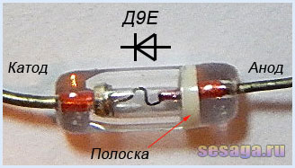
Diodes VD1 – VD4 any from the D9 series. A colored stripe is applied to the diode body on the anode side, identifying the letter of the diode.
As a rectifier assembled on diodes VD5 - VD8, a ready-made miniature diode bridge is used, designed for a voltage of 50V and a current of at least 200 mA.

If you use rectifier diodes instead of a ready-made bridge, you will have to slightly adjust the printed circuit board, or even move the diode bridge outside the main board of the set-top box and assemble it on a separate small board.
For self-assembly of the bridge, the diodes are taken with the same parameters as the factory bridge. Any rectifier diodes from the KD105, KD106, KD208, KD209, KD221, D229, KD204, KD205, 1N4001 - 1N4007 series are also suitable. If you use diodes from the KD209 or 1N4001 - 1N4007 series, then the bridge can be assembled directly from the printed circuit board directly on the contact pads of the board.
LEDs are standard with yellow, red, blue and green colors. Each channel uses 6 pieces:

Transistors VT1 and VT2 from the KT361 series with any letter index.

Transistors VT3, VT4, VT5, VT6 from the KT502 series with any letter index.

Voltage stabilizer type KREN5A with any letter index (imported analogue 7805). If you use nine-volt KREN8A or KREN8G (imported analogue 7809), then resistor R22 is not installed. Instead of a resistor, a jumper is installed on the board, which will connect the middle pin of the microcircuit to the negative bus, or this resistor is not provided at all during the manufacture of the board.

To connect the set-top box to the sound source, a three-pin jack connector is used. The cable is taken from a computer mouse.

Power transformer - ready-made or home-made with a power of at least 5 W with a voltage on the secondary winding of 12 - 15 V at a load current of 200 mA.
In addition to the article, watch the first part of the video, which shows the initial stage of assembling a color music console
This ends the first part.
If you are tempted make color music using LEDs, then select the parts and be sure to check the serviceability of diodes and transistors, for example. And we will carry out the final assembly and configuration of the color and music console.
Good luck!
Literature:
1. I. Andrianov “Attacks for radio receivers.”
2. Radio 1990 No. 8, B. Sergeev “Simple color and music consoles.”
3. Operating manual for the “Start” radio designer.
This color and music console implements the effect of “running dot” and “chaos” accompanied by musical accompaniment. The set-top box is not connected to the source of the electrical signal by wires, but receives the signal using a microphone. You simply place it in a room where music is playing, and it itself begins to work to the beat. The device consists of a transistor microphone amplifier, a microcircuit 176IE12 , which contains two frequency dividers and elements of a master oscillator, switches on transistors VT2-VT5 and LEDs with current-limiting resistors. The circuit is a bit reminiscent of the famous light-music from magazines of the 80s, where the same microcircuit controlled thyristors that switched 220V incandescent lamps.

Drawing of the board of the LED color and music set-top box
The music signal, amplified by transistor VT1, is supplied through capacitor C2 to the input of the counter generator DD1. Resistors R4, R5 create negative feedback of the generator and bring it into active mode, due to which it responds to the signal from the microphone amplifier. After that, pulses are sent to the input of the second counter, and pulses of different frequencies are formed at its outputs T1-T4, shifted by a quarter of a period relative to each other. These pulses open transistors VT2-VT5 and the corresponding LEDs begin to glow.

Using a variable resistor R4, you can adjust the sensitivity, thereby achieving the “running dot” or “chaos” effect. By connecting a capacitor between pins 12 and 14 of the DD1 microcircuit, the “running dot” effect will be realized without musical accompaniment, therefore the set-top box from the CMU will turn into an SDU (the capacitance of the capacitor is selected, the flash frequency *2200pf depends on it).

Microphone amplifier transistor KT3102 replace with series transistors KT315 . Tests have shown that the device is operational at a supply voltage of 7 to 9 V. Blue and red LEDs of increased brightness are used. But LEDs of other colors are also suitable. For the specified supply voltage range, instead of one LED, you can install two connected in series. The color music power supply is a network stabilized power supply with an output current of 200 mA or a battery.

Video of the CMP operation
It's hard to find a person who doesn't like listening to music. To satisfy this desire, high-quality music centers, speakers and other devices are purchased. To get even more pleasure, many people think about creating special color effects that can decorate any sound and create a romantic atmosphere on a date or a fun mood when organizing a holiday party. Color music, like music centers, can be purchased, or you can make it yourself. The best option is to make color music using LEDs with your own hands according to one of the proposed schemes.
Advantages of LED products
The modern electronics market presents a wide variety of LED strips that have a wide variety of color effects. With their help, you can create high-quality spot lighting; it is possible to create light music with flashing or blurry effects.
Unlike conventional light bulbs, LEDs have many positive characteristics. Among the main advantages of LED strips are:
- wide and varied range of colors;
- rendering rich colors;
- different design options - rulers, modules, discrete elements, RGB strips;
- high response speed;
- minimum amount of energy consumed.
The ribbons can be used at home, in clubs and cafes, and can be used to effectively illuminate shop windows. This article will describe in more detail the option of LED color music for ordinary home use.
Simple circuit with one lamp
To begin with, it’s worth studying a simple color music scheme. This is a device that consists of one LED, transistor and resistor. Power for such color music can be supplied from a constant current source with a voltage of 6-12 volts. The device operates on the principle of an amplification stage with a common emitter. The impact in the form of a signal varying in frequency and amplitude arrives at the main base. As soon as the oscillation frequency exceeds a certain threshold value, the transistor opens and the LED immediately flashes.

This scheme of simple color music using LEDs has one drawback - the rate of blinking of the LED depends entirely on the level of the sound signal produced. In other words, the light effect will be activated only at a certain level of volume produced by the music center. When the sound intensity decreases, the glow will be constant with occasional winks.
Scheme with one-color ribbon
This color music on a transistor is assembled using an LED strip in the load. To organize such color music, you will need to increase the power supply to 12 V, find and install a transistor with a maximum collector current that exceeds the load current, and you will also need to recalculate the total value of the resistor. This color music is quite simple, made on one single-color LED strip and is ideal for beginner radio amateurs. You can assemble it without any problems at home.
Simple three-channel circuit
To get color music that is free of all the disadvantages listed above, you should use a special three-channel sound converter. Such a circuit is powered from an LED strip with a constant voltage of 9 V and is able to effectively illuminate one or two LEDs in each channel. Among the main structural elements that characterize such a color-musical scheme are:
- three independent amplifier stages, which are assembled using transistors of the KT315 (KT3102) category;
- LEDs of different colors are included in the transistor load;
- For the pre-amplification element, a network small step-down transformer can be used.

The incoming signal is fed to the secondary winding of the transformer, which in turn performs two main functions - it decouples two devices at the galvanic level, and also amplifies the sound from the main linear output. After this, the signal is fed to three parallel and connected filters assembled on the basis of RC circuits. They operate on an individual frequency band, which directly depends on the value of the capacitor and resistor.
Color music with RGB tape
This attachment circuit operates on 12 volts and is ideal for installation on a car. This color music optimally combines the main functions of the previously discussed schemes and is able to work both in the lamp mode and in the color music mode. The second mode is achieved through special contactless control of the RGB strip via a microphone. As for the lamp mode, it is based on the simultaneous launch of the green, red and blue LED at full power. The mode can be selected using a special switch located on a special board.
To understand how this attachment works, it is worth studying its sequence of actions. The main source of the signal here is a microphone, which converts sound vibrations emanating from the phonogram. The received signal is insignificant and therefore requires amplification. This can be achieved by using a transistor or a special operational amplifier. After this, the automatic AGC level controller starts. It effectively keeps sound fluctuations within reasonable limits and prepares it for subsequent processing. Built-in filters divide the signal into three parts, each of which operates in one specific frequency range. Finally, you just need to amplify the previously prepared current signal. For this purpose, special transistors are used that operate in key mode.

Purchase of a ready-made CMU
If you don’t want to make a color music system for use at home, you can purchase a CMU, that is, a color music installation. This is a ready-made functional solution that includes a controller. It will process the sound, converting it into a light and music visual representation. In the process of reproducing the light, its intensity and color scheme will change, thereby creating the effect of a real disco. The CMU device also includes a panel with built-in diodes.
These devices may be based on a spectral decomposition into frequencies, where each of them will have a specific color scheme or preset adjustments with a variety of effects and their alternation. They can be configured using the included remote control.
Important! Modern CMUs are very simple to install and configure. This is an ideal solution for organizing a home party or disco.
Conclusion
There are quite a lot of schemes for independently performing color music settings. You can choose a fairly simple option, where the color of the RGB tape will simply change, to quite complex ones, which in the process of work will create a large number of different effects, overflows and attenuations. Depending on your skills, you can choose and execute the appropriate option. It is enough to work a little and create something truly unique; it will be lighting equipment that delights with the shimmer of a wide variety of color shades. Also, do not forget that there is always the opportunity to buy a ready-made color music solution and fill your home with color shades and joy.
Do-it-yourself color music - what could be more pleasant and interesting for a radio amateur, because it is not difficult to assemble if you have a good circuit.
In modern radio engineering there is a huge variety of radio elements and LEDs, the advantages of which are difficult to doubt. A wide range of colors, bright and rich light, high speed of response of various elements, low energy consumption. This list of advantages can be continued endlessly.
The principle of operation of color music: LEDs assembled according to the circuit blink from an existing sound source (this can be a player or a radio and speakers) at a certain frequency.
Advantages of using LEDs over those previously used in CMU:
- luminous saturation of light and a wide color range;
- good speed;
- low energy consumption.
The simplest schemes
A simple color music that can be assembled has one LED and is powered by a 6–12 V DC source.
You can assemble the above circuit using an LED strip and selecting the necessary transistor. The disadvantage is that there is a dependence on the sound level. In other words, the full effect can be observed only at one sound level. If you lower the volume, there will be a rare blinking, and if you increase the volume, a constant glow will remain.
This drawback can be eliminated using a three-channel sound converter. Below is a simple circuit; it is not difficult to assemble it with your own hands using transistors.

Color music circuit with three-channel sound converter
This circuit requires a 9-volt power supply, which will allow the LEDs in the channels to light. To assemble three amplification stages, you will need KT315 transistors (analogous to KT3102). Multi-colored LEDs are used as a load. A step-down transformer is used for amplification. Resistors perform the function of adjusting LED flashes. The circuit contains filters for passing frequencies.
The scheme can be improved. To do this, you need to add brightness with 12 V incandescent light bulbs. You will need control thyristors. The entire device must be powered from a transformer. You can already work according to this simplest scheme. Color music using thyristors can be assembled even by a novice radio technician.

How to make color music using LEDs with your own hands? The first thing you need to do is select an electrical circuit.
Below is a diagram of a light and music system with an RGB strip. For such an installation, a 12 volt power supply is required. It can work in two modes: as a lamp and as a color music. The mode is selected by a switch installed on the board.

Manufacturing stages
It is necessary to make a printed circuit board. To do this, you need to take foil fiberglass with dimensions of 50 x 90 mm and a thickness of 0.5 mm. The board manufacturing process consists of several stages:
- preparation of foil PCB;
- drilling holes for parts;
- drawing paths;
- etching.

The board is ready, components have been purchased. Now begins the most crucial moment - the wiring of radio elements. The final result will depend on how carefully they are installed and sealed.

We assemble our printed circuit board with the components soldered on it into such an accessible lampshade.

Brief description of radioelements
Radioelements for an electrical circuit are quite affordable; purchasing them at your nearest electrical goods store will not be difficult.
For color and musical accompaniment, wirewound resistors with a power of 0.25–0.125 W are suitable. The amount of resistance can always be determined by the colored stripes on the body, knowing the order in which they are applied. Trimmer resistors can be both domestic and imported.
Capacitors produced by industry are divided into oxide and electrolytic. It won’t be difficult to select the ones you need by doing basic calculations. Some oxide capacitors may have a polarity that must be observed during installation.
You can take a ready-made diode bridge, but if you don’t have it, then a rectifier bridge can be easily assembled using diodes of the KD or 1N4007 series. LEDs are taken as usual, with a multi-colored glow. The use of LED RGB strips is a promising direction in radio electronics.

LED RGB strip
Possibility of assembling a color and music console for a car
If you manage to please with color music from an LED strip made by yourself, then a similar installation with a built-in radio can be made for a car. It is easy to assemble and quick to set up. It is proposed to place the set-top box in a plastic case, which can be purchased in the electrical and radio engineering department. The installation is reliably protected from moisture and dust. It is easy to install behind the dashboard of your car.
You can also make a similar case yourself using plexiglass.
The plates of the required dimensions are selected, two holes are made in the first part (for power supply), and all parts are sanded. We assemble everything using a heat gun.
An excellent lighting effect is achieved if you use multi-colored (RGB) tape.
Conclusion
The well-known saying “it is not the gods who burn the pots” remains relevant today. A diverse range of electronic components gives craftsmen wide scope for imagination. DIY color music on LEDs is one of the manifestations of limitless creativity.
To make color music using LEDs with your own hands, you need to have at least a basic understanding of electronics, know how to use a soldering iron and understand drawings correctly.
Principle of operation
This device is based on a method of privately converting sound and transmitting it to certain channels in order to control the light source. As a result, it turns out that depending on the musical parameters, the operation of the circuit will fully correspond to it. It is on these principles that the collection scheme is based.
Typically, three or more different colors are used to create color effects. Red, blue and green are most often used. By mixing in certain combinations with a clear duration, they create a real holiday.
The division of frequencies into high, medium, and low occurs due to RC and LC filters, which are mounted and configured in a system in which LEDs are used.
Filters are configured according to the following parameters:
- For low-frequency parts, up to 300 hertz is allocated, and it is often red;
- Mid – 250 – 2500Hz, green;
- Anything above the 2000 hertz mark is converted by high-frequency filters, and it is on this element that the blue tint LED will work.
In order to obtain a variety of color shades during operation, the division into frequencies should be carried out with slight overlap. In the scheme under consideration, the choice of color is not so important, because if you wish, you can use different LEDs, rearrange their location and experiment; here everything depends on the desire of the master. An unusual color program coupled with fluctuations can have a significant impact on the final result. To make adjustments, there are also indicators such as frequency or number of channels.
Based on this information, it can be understood that color music can involve a significant number of different shades, as well as direct programming of each.
What is needed to make color music
To create such an installation, you can only use fixed resistors, the power of which is 0.25-0.125. To find out the resistance value, look at the strips located on the base.
The circuit also includes R3 resistors and trimmed R. The main condition is the ability to install them on the board on which the installation is being made. If we talk about capacitors, then when working, we take products whose operating voltage is at least 16 volts (any type is suitable). If finding capacitors C7 is problematic, then parallel connection of a pair of smaller capacitances is allowed, then you will get the necessary values. The capacitors C6, as well as C1, used in the variant under study must be started at 10 volts, and the rest at 25. In the case when outdated Soviet parts need to be replaced with imported ones, it is necessary to understand that they are all designated differently. Therefore, take care in advance to determine the polarity of the elements that will be mounted. Otherwise, the circuit may fail.

Also, to create color music with your own hands, you will need a diode bridge, the operating current of which is 200 milliamps and the voltage is 50V. In a situation where installing a finished bridge is not possible, it can be created using rectifier diodes. For convenience, they can be removed from the board and mounted separately, using a smaller workspace.
To create one channel you will need 6 LEDs of all colors. If we talk about transistors, then VT2 and VT1 are quite suitable; here the index does not play a special role.