Inverse Ohm's Law. The most important law of electrical engineering is Ohm's law
Ohm's law for a complete circuit is an empirical (derived from experiment) law that establishes the relationship between current strength, electromotive force (EMF) and external and internal resistance in a circuit.
When conducting actual studies of the electrical characteristics of DC circuits, it is necessary to take into account the resistance of the current source itself. Thus, in physics, a transition is made from an ideal current source to a real current source, which has its own resistance (see Fig. 1).
Rice. 1. Image of ideal and real current sources
Consideration of a current source with its own resistance requires the use of Ohm's law for the complete circuit.
Let us formulate Ohm's law for a complete circuit as follows (see Fig. 2): the current strength in a complete circuit is directly proportional to the emf and inversely proportional to the total resistance of the circuit, where total resistance is understood as the sum of external and internal resistances.

Rice. 2. Diagram of Ohm's law for a complete circuit.

- R – external resistance [Ohm];
- r – resistance of the EMF source (internal) [Ohm];
- I – current strength [A];
- ε – EMF of the current source [V].
Let's look at some problems on this topic. Problems on Ohm's law for a complete circuit are usually given to 10th grade students so that they can better understand the specified topic.
I. Determine the current in a circuit with a light bulb, a resistance of 2.4 Ohms and a current source whose emf is 10 V and the internal resistance is 0.1 Ohms.
By definition of Ohm's law for a complete circuit, the current strength is equal to:
II. Determine the internal resistance of a current source with an emf of 52 V. If it is known that when this current source is connected to a circuit with a resistance of 10 Ohms, the ammeter shows a value of 5 A.
Let's write Ohm's law for the complete circuit and express the internal resistance from it:
III. One day a schoolboy asked his physics teacher: “Why does the battery run out?” How to correctly answer this question?
We already know that a real source has its own resistance, which is determined either by the resistance of electrolyte solutions for galvanic cells and batteries, or by the resistance of conductors for generators. According to Ohm's law for a complete circuit:

therefore, the current in the circuit may decrease either due to a decrease in emf or due to an increase in internal resistance. The battery's emf value is almost constant. Consequently, the current in the circuit decreases due to an increase in internal resistance. So, the “battery” runs out, as its internal resistance increases.
We are starting to publish materials in a new section “” and in today’s article we will talk about fundamental concepts, without which not a single electronic device or circuit can be discussed. As you may have guessed, I mean current, voltage and resistance😉 In addition, we will not ignore the law that determines the relationship of these quantities, but I won’t get ahead of ourselves, let’s move gradually.
So let's start with the concept voltage.
Voltage.
By definition voltage is the energy (or work) that is expended to move a unit positive charge from a point with a low potential to a point with a high potential (i.e., the first point has a more negative potential compared to the second). We remember from the physics course that the potential of an electrostatic field is a scalar quantity equal to the ratio of the potential energy of a charge in the field to this charge. Let's look at a small example:

There is a constant electric field in space, the intensity of which is equal to E. Consider two points located at a distance d from each other. So the voltage between two points is nothing more than the potential difference at these points:
At the same time, do not forget about the connection between the electrostatic field strength and the potential difference between two points:
And as a result, we get a formula connecting stress and tension:
In electronics, when considering various circuits, voltage is still considered to be the potential difference between points. Accordingly, it becomes clear that voltage in a circuit is a concept associated with two points in the circuit. That is, to say, for example, “voltage in a resistor” is not entirely correct. And if they talk about voltage at some point, then they mean the potential difference between this point and "earth". This is how we smoothly arrived at another most important concept in the study of electronics, namely the concept "Earth":) So here it is "earth" in electrical circuits, it is most often accepted to consider the point of zero potential (that is, the potential of this point is equal to 0).
Let's say a few more words about the units that help characterize the quantity voltage. The unit of measurement is Volt (V). Looking at the definition of the concept of voltage, we can easily understand that to move a charge of magnitude 1 pendant between points having a potential difference 1 Volt, it is necessary to do work equal to 1 Joule. With this, everything seems to be clear and we can move on 😉
And next in line we have one more concept, namely current.
Current, current strength in a circuit.
What is it electric current?
Let's think about what will happen if charged particles, for example, electrons, come under the influence of an electric field... Consider a conductor to which a certain voltage:

From the direction of the electric field strength ( E) we can conclude that title="Rendered by QuickLaTeX.com" height="16" width="60" style="vertical-align: -4px;"> (вектор напряженности всегда направлен в сторону уменьшения потенциала). На каждый электрон начинает действовать сила:!}
Where e is the charge of the electron.
And since the electron is a negatively charged particle, the force vector will be directed in the direction opposite to the direction of the field strength vector. Thus, under the influence of force, particles, along with chaotic motion, also acquire directional motion (velocity vector V in the figure). As a result, there arises electric current 🙂
Current is the ordered movement of charged particles under the influence of an electric field.
The important point is that current is assumed to flow from a point with a more positive potential to a point with a more negative potential, even though the electron is moving in the opposite direction.
Not only electrons can act as charge carriers. For example, in electrolytes and ionized gases, the flow of current is primarily associated with the movement of ions, which are positively charged particles. Accordingly, the direction of the force vector acting on them (and at the same time the velocity vector) will coincide with the direction of the vector E. And in this case, no contradiction will arise, because the current will flow exactly in the direction in which the particles are moving :)
In order to estimate the current in a circuit, they came up with such a quantity as current strength. So, current strength (I) is a quantity that characterizes the speed of movement of an electric charge at a point. The unit of current is Ampere. The current strength in the conductor is equal to 1 Ampere, if for 1 second charge passes through the cross section of the conductor 1 pendant.
We have already covered the concepts current and voltage, now let's figure out how these quantities are related. And for this we have to study what it is conductor resistance.
Conductor/circuit resistance.
The term “ resistance” already speaks for itself 😉
So, resistance– physical quantity characterizing the properties of a conductor to hinder ( resist) the passage of electric current.
Consider a copper conductor of length l with a cross-sectional area equal to S:

Conductor resistance depends on several factors:
Specific resistance is a tabular value.
The formula with which you can calculate the resistance of a conductor is as follows:
For our case it will be equal 0.0175 (Ohm * sq. mm/m)– resistivity of copper. Let the length of the conductor be 0.5 m, and the cross-sectional area is equal to 0.2 sq. mm. Then:
As you already understood from the example, the unit of measurement is resistance is Ohm 😉
WITH conductor resistance everything is clear, it's time to study the relationship voltage, current and circuit resistance.
And here the fundamental law of all electronics comes to our aid - Ohm's law:
The current in a circuit is directly proportional to the voltage and inversely proportional to the resistance of the section of the circuit in question.
Let's consider the simplest electrical circuit:

As follows from Ohm's law, voltage and current in a circuit are related as follows:
Let the voltage be 10 V and the circuit resistance be 200 ohms. Then the current in the circuit is calculated as follows:
As you can see, everything is not difficult :)
Perhaps this is where we will finish today’s article, thank you for your attention and see you soon! 🙂
The basic law of electrical engineering, with the help of which electrical circuits can be studied and calculated, is Ohm's law, which establishes the relationship between current, voltage and resistance. It is necessary to clearly understand its essence and be able to use it correctly when solving practical problems. Often mistakes are made in electrical engineering due to the inability to correctly apply Ohm's law.
Ohm's law for a circuit section states: current is directly proportional to voltage and inversely proportional to resistance.
If you increase the voltage acting in an electrical circuit several times, then the current in this circuit will increase by the same amount. And if you increase the circuit resistance several times, the current will decrease by the same amount. Similarly, the greater the pressure and the less resistance the pipe provides to the movement of water, the greater the water flow in the pipe.
In a popular form, this law can be formulated as follows: the higher the voltage at the same resistance, the higher the current, and at the same time, the higher the resistance at the same voltage, the lower the current.
To express Ohm's law most simply mathematically, it is believed that The resistance of a conductor that carries a current of 1 A at a voltage of 1 V is 1 ohm.
The current in amperes can always be determined by dividing the voltage in volts by the resistance in ohms. That's why Ohm's law for a circuit section is written by the following formula:
I = U/R.
Magic triangle
Any section or element of an electrical circuit can be characterized using three characteristics: current, voltage and resistance.
How to use Ohm's triangle: close the desired value - the other two symbols will give the formula for calculating it. By the way, Ohm's law is called only one formula from the triangle - the one that reflects the dependence of current on voltage and resistance. The other two formulas, although they are its consequences, have no physical meaning.

Calculations performed using Ohm's law for a section of a circuit will be correct when the voltage is expressed in volts, resistance in ohms and current in amperes. If multiple units of measurement of these quantities are used (for example, milliamps, millivolts, megaohms, etc.), then they should be converted to amperes, volts and ohms, respectively. To emphasize this, sometimes the Ohm's law formula for a section of a circuit is written like this:
ampere = volt/ohm
You can also calculate the current in milliamps and microamps, while the voltage should be expressed in volts, and the resistance in kilo-ohms and mega-ohms, respectively.
Other articles about electricity in a simple and accessible presentation:
Calculating voltage using Ohm's law can be illustrated with the following example. Let a current of 5 mA pass through a section of a circuit with a resistance of 10 kOhm and you need to determine the voltage in this section.
Multiplying I = 0.005 A at R -10000 Ohm, we get a voltage equal to 5 0 V. We could get the same result by multiplying 5 mA by 10 kOhm: U = 50 V
In electronic devices, current is usually expressed in milliamps and resistance in kilo-ohms. Therefore, it is convenient to use these units of measurement in calculations according to Ohm’s law.
Ohm's law also calculates resistance if the voltage and current are known. The formula for this case is written as follows: R = U/I.
Resistance is always a ratio of voltage to current. If the voltage is increased or decreased several times, the current will increase or decrease by the same number of times. The ratio of voltage to current, equal to resistance, remains unchanged.
The formula for determining resistance should not be understood to mean that the resistance of a given conductor depends on the outflow and voltage. It is known that it depends on the length, cross-sectional area and material of the conductor. In appearance, the formula for determining resistance resembles the formula for calculating current, but there is a fundamental difference between them.
The current in a given section of the circuit really depends on voltage and resistance and changes when they change. And the resistance of a given section of the circuit is a constant value, independent of changes in voltage and current, but equal to the ratio of these values.
When the same current passes in two sections of a circuit, and the voltages applied to them are different, it is clear that the section to which the greater voltage is applied has a correspondingly greater resistance.
And if, under the influence of the same voltage, different currents flow in two different sections of the circuit, then the smaller current will always be in the section that has greater resistance. All this follows from the basic formulation of Ohm’s law for a section of a circuit, i.e., from the fact that the greater the current, the greater the voltage and the lower the resistance.
We will show the calculation of resistance using Ohm's law for a section of a circuit using the following example. Let you need to find the resistance of the section through which a current of 50 mA passes at a voltage of 40 V. Expressing the current in amperes, we get I = 0.05 A. Divide 40 by 0.05 and find that the resistance is 800 Ohms.
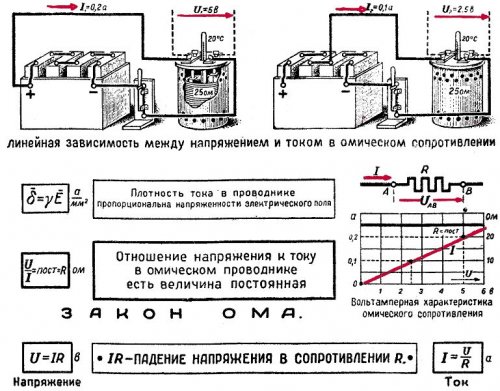
Ohm's law can be clearly represented as the so-called current-voltage characteristics. As you know, a direct proportional relationship between two quantities is a straight line passing through the origin. This dependence is usually called linear.
In Fig. Figure 2 shows as an example a graph of Ohm's law for a section of a circuit with a resistance of 100 Ohms. The horizontal axis represents voltage in volts, and the vertical axis represents current in amperes. The scale of current and voltage can be chosen as desired. A straight line is drawn so that for any point the ratio of voltage to current is 100 Ohms. For example, if U = 50 V, then I = 0.5 A and R = 50: 0.5 = 100 Ohm.
Rice. 2. Ohm's law (volt-ampere characteristic)
The graph of Ohm's law for negative values of current and voltage has the same appearance. This indicates that the current in the circuit flows equally in both directions. The greater the resistance, the less current is obtained at a given voltage and the more flat the straight line is.
Devices in which the current-voltage characteristic is a straight line passing through the origin of coordinates, i.e., the resistance remains constant when the voltage or current changes, are called linear devices. The terms linear circuits and linear resistances are also used.
There are also devices in which the resistance changes when the voltage or current changes. Then the relationship between current and voltage is expressed not according to Ohm’s law, but in a more complex way. For such devices, the current-voltage characteristic will not be a straight line passing through the origin of coordinates, but will be either a curve or a broken line. These devices are called nonlinear.
Mnemonic diagram for Ohm's law
Georg Simon Ohm began his research inspired by the famous work of Jean Baptiste Fourier, “The Analytical Theory of Heat.” In this work, Fourier represented the heat flow between two points as a temperature difference, and associated the change in heat flow with its passage through an irregularly shaped obstacle made of heat-insulating material. Similarly, Ohm caused the occurrence of electric current by a potential difference.
Based on this, Ohm began to experiment with different conductor materials. In order to determine their conductivity, he connected them in series and adjusted their length so that the current strength was the same in all cases.
It was important for such measurements to select conductors of the same diameter. Ohm, measuring the conductivity of silver and gold, obtained results that, according to modern data, are not accurate. Thus, Ohm's silver conductor conducted less electric current than gold. Om himself explained this by saying that his silver conductor was coated with oil and because of this, apparently, the experiment did not give accurate results.
However, this was not the only problem that physicists, who at that time were engaged in similar experiments with electricity, had problems with. Great difficulties in obtaining pure materials without impurities for experiments and difficulties in calibrating the diameter of the conductor distorted the test results. An even bigger snag was that the current strength was constantly changing during the tests, since the source of the current was alternating chemical elements. Under such conditions, Ohm derived a logarithmic dependence of the current on the resistance of the wire.
A little later, the German physicist Poggendorff, who specialized in electrochemistry, suggested that Ohm replace the chemical elements with a thermocouple made of bismuth and copper. Om began his experiments again. This time he used a thermoelectric device powered by the Seebeck effect as a battery. To it he connected in series 8 copper conductors of the same diameter, but of different lengths. To measure the current, Ohm suspended a magnetic needle over the conductors using a metal thread. The current running parallel to this arrow shifted it to the side. When this happened, the physicist twisted the thread until the arrow returned to its original position. Based on the angle at which the thread was twisted, one could judge the value of the current.
As a result of a new experiment, Ohm came to the formula:
X = a / b + l
Here X– intensity of the magnetic field of the wire, l– wire length, a– constant source voltage, b– resistance constant of the remaining elements of the circuit.
If we turn to modern terms to describe this formula, we get that X– current strength, A– EMF of the source, b + l– total circuit resistance.
Ohm's law for a circuit section
Ohm's law for a separate section of a circuit states: the current strength in a section of a circuit increases as the voltage increases and decreases as the resistance of this section increases.
I=U/R
Based on this formula, we can decide that the resistance of the conductor depends on the potential difference. From a mathematical point of view, this is correct, but from a physics point of view, it is false. This formula is applicable only for calculating the resistance on a separate section of the circuit.
Thus, the formula for calculating the conductor resistance will take the form:
R = p ⋅ l / s
Ohm's law for a complete circuit
The difference between Ohm's law for a complete circuit and Ohm's law for a section of a circuit is that now we must take into account two types of resistance. This is “R” the resistance of all components of the system and “r” the internal resistance of the source of electromotive force. The formula thus takes the form:
I = U / R + r
Ohm's law for alternating current
Alternating current differs from direct current in that it changes over certain time periods. Specifically, it changes its meaning and direction. To apply Ohm's law here, you need to take into account that the resistance in a circuit with direct current may differ from the resistance in a circuit with alternating current. And it differs if components with reactance are used in the circuit. Reactance can be inductive (coils, transformers, chokes) or capacitive (capacitor).
Let's try to figure out what the real difference is between reactive and active resistance in a circuit with alternating current. You should already understand that the value of voltage and current in such a circuit changes over time and, roughly speaking, have a wave form.
If we diagram how these two values change over time, we get a sine wave. Both voltage and current rise from zero to a maximum value, then, falling, pass through zero and reach a maximum negative value. After this, they rise again through zero to the maximum value and so on. When it is said that current or voltage is negative, it means that it moves in the opposite direction.
The whole process occurs with a certain frequency. The point where the voltage or current value from the minimum value rising to the maximum value passes through zero is called phase.
In fact, this is just a preface. Let's return to reactive and active resistance. The difference is that in a circuit with active resistance, the current phase coincides with the voltage phase. That is, both the current value and the voltage value reach a maximum in one direction at the same time. In this case, our formula for calculating voltage, resistance or current does not change.
If the circuit contains reactance, the phases of the current and voltage shift from each other by ¼ of a period. This means that when the current reaches its maximum value, the voltage will be zero and vice versa. When inductive reactance is applied, the voltage phase "overtakes" the current phase. When capacitance is applied, the current phase "overtakes" the voltage phase.
Formula for calculating the voltage drop across inductive reactance:
U = I ⋅ ωL
Where L is the inductance of the reactance, and ω – angular frequency (time derivative of the oscillation phase).
Formula for calculating the voltage drop across capacitance:
U = I / ω ⋅ C
WITH– reactance capacitance.
These two formulas are special cases of Ohm's law for variable circuits.
The complete one will look like this:
I=U/Z
Here Z– The total resistance of a variable circuit is known as impedance.
Scope of application
Ohm's law is not a basic law in physics, it is just a convenient dependence of some values on others, which is suitable in almost any practical situation. Therefore, it will be easier to list situations when the law may not work:
- If there is inertia of charge carriers, for example in some high-frequency electric fields;
- In superconductors;
- If the wire heats up to such an extent that the current-voltage characteristic ceases to be linear. For example, in incandescent lamps;
- In vacuum and gas radio tubes;
- In diodes and transistors.
One of the most applied laws in electrical engineering. This law reveals the relationship between three most important quantities: current, voltage and resistance. This connection was discovered by Georg Ohm in the 1820s, which is why this law received its name.
Formulation of Ohm's law next:
The amount of current in a section of a circuit is directly proportional to the voltage applied to that section and inversely proportional to its resistance.
This dependence can be expressed by the formula:
Where I is the current strength, U is the voltage applied to the circuit section, and R is the electrical resistance of the circuit section.
So, if two of these quantities are known, the third can be easily calculated.
Ohm's law can be understood using a simple example. Let's say we need to calculate the resistance of the filament of a flashlight light bulb and we know the operating voltage of the light bulb and the current required for its operation (the light bulb itself, so you know, has a variable resistance, but for the example we will take it as constant). To calculate the resistance, you need to divide the voltage by the current. How to remember the formula of Ohm's law in order to carry out calculations correctly? And it's very easy to do! You just need to make yourself a reminder as in the figure below.
Now, if you cover any of the quantities with your hand, you will immediately understand how to find it. If you close the letter I, it becomes clear that to find the current you need to divide the voltage by the resistance.
Now let's figure out what the words “directly proportional and inversely proportional” mean in the formulation of the law. The expression “the amount of current in a section of a circuit is directly proportional to the voltage applied to this section” means that if the voltage in a section of a circuit increases, then the current in that section will also increase. In simple words, the greater the voltage, the greater the current. And the expression “inversely proportional to its resistance” means that the greater the resistance, the less the current will be.
Let's consider an example with the operation of a light bulb in a flashlight. Let's say that the flashlight requires three batteries to operate, as shown in the diagram below, where GB1 - GB3 are batteries, S1 is a switch, HL1 is a light bulb.

Let us assume that the resistance of the light bulb is conditionally constant, although as it heats up its resistance increases. The brightness of the light bulb will depend on the current strength; the higher it is, the brighter the light bulb burns. Now, imagine that instead of one battery we inserted a jumper, thereby reducing the voltage.
What will happen to the light bulb?
It will shine more dimly (the current strength has decreased), which confirms Ohm's law:
the lower the voltage, the lower the current.
This is how this physical law that we encounter in everyday life works simply.
Bonus, a comic picture especially for you that explains Ohm’s law no less colorfully.

This was a review article. We talk about this law in more detail in the next article "", looking at everything using other more complex examples.
If you don’t succeed with physics, English for children (http://www.anylang.ru/order-category/?slug=live_language) as an alternative development option.