Schematic electrical diagrams. Training course
Manufacturers of portable equipment, workstations, laptop computers, mobile phones and video games use flat panel displays to display text and images. Mechanical potentiometers have traditionally been used to adjust display contrast and brightness. However, today they are being replaced by digital control devices. To illustrate a circuit with digital brightness and contrast control, two digital potentiometers from the Dallastat DS1668/DS1669 family will be used, which in practice can be replaced by any other digital potentiometer.
Models DS1668/DS1669 were chosen due to their simple push-button interface for controlling the position of the slider. The push-button interface is most convenient for adjusting the contrast of flat LCD displays and is in essence very close to traditional mechanical potentiometers. Most importantly, the DS1668/DS1669 have a built-in non-volatile memory unit that retains the position of the middle pin after the system is powered off. Replacing a mechanical component with a digital one provides additional benefits in the areas of control, reliability and automation of the final product. In addition, the DS1669 can be controlled via a central processor. This flexibility in application is not available when working with mechanical variable resistors. Because the DS1669 is an integrated monolithic solution with no moving parts, its reliability compared to traditional solutions is undeniable. In the contrast adjustment circuit, the DS1669 potentiometer can be located on the board away from the button of the corresponding section of the display control panel. DS1669 are available in standard DIP-8 and SOIC-8 packages for automated board mounting.
Liquid crystal displays.
LCD displays can be divided into two categories: alphanumeric and graphics modules. Each of them, depending on the power supply requirements, has a control voltage input, which in most cases can be varied to adjust the contrast. The display contrast may change due to changes in the applied control voltage or ambient temperature. Temperature changes usually have the undesirable effect of significantly reducing screen contrast. A variable resistor is used to regulate the control voltage in cases where an increase in voltage can overcome the effect of temperature shift. But the most important point is that the potentiometer allows you to satisfy any user desires in relation to the brightness and contrast of the screen.
Alphanumeric LCD modules.
Alphanumeric indicators are small in size and are used in portable systems. The power requirements for such modules boil down to a single 5V power supply that powers both the LCD display and the logic driver. Additional voltage is required to provide power to the LCD control functions (Fig. 1). The control voltage of the VO module is taken from the potentiometer VR. The typical nominal value of such potentiometers ranges from 10-20 kΩ. The DS1669 series potentiometer models have the same ratings.

The DS1669 potentiometer is suitable for any LCD modules with similar power conditions. Figure 2 shows a DS1669 configuration that meets all the power and control voltage requirements of the LCD modules shown in Diagram 65. The device is wired as a simple push button to control the movement of the middle pin. You can also use a double button topology. One- and two-button controls are described below. The slider pin, RW, of the DS1669 potentiometer is directly connected to the control voltage pin of the LCD module, VO. For the power supply circuit shown in Fig. 1, no additional components are required to operate the DS1669 with the LCD module.
Graphic LCD modules.
 Graphic modules are significantly larger in size than alphanumeric displays and operate with different supply voltages. As shown in Figure 3, the power supply for such modules consists of a 5V power supply to power the logic and a VLCDC input to power the module. The control voltage VO, which controls contrast, is taken from the combined 5V logic source and VLCD module power supply through potentiometer R. As is the case with alphanumeric displays, the nominal value of the potentiometer ranges from 10 -20 kOhm. The voltage at the VO pin ranges from 0 to (VLCD+ 5V) V. The VLCD supply voltage depends on the type of graphic display used.
The VO voltage range prevents direct use of the DS1669, as well as other potentiometers manufactured by Dallas Semiconductor. To mitigate the difficulties with the maximum motor current limit and the high voltage required for this circuit, a digital potentiometer is used in conjunction with an op-amp (Fig. 4). The purpose of an op amp is to generate a control voltage, VO, which is outside of specification when driven by a digital potentiometer. In addition, the op-amp limits the amount of current flowing through the motor and provides the full control voltage range for the LCD module. The 5V power supply used to power the module logic is also used to power the DS1669 potentiometer (see Figure 4).  The potentiometer acts as an attenuator for the 5V input signal to the non-inverted output of the op-amp. The op-amp output controls the LCD module's contrast voltage, VO, and is calculated by the formula: where N is the number of potentiometer positions. The nominal values of resistors R1 and R2 are selected according to the formula: The selection of resistors R1 and R2 allows you to change the output voltage of the operational amplifier depending on the nominal power supply of the LCD graphics module (supplied to the VO pin). The middle pin pin is directly connected to the non-inverting pin of the op-amp as shown in the diagram. It is also recommended to use a D1 Schottky diode (type 1N5818 or equivalent) to provide additional protection against power surges during power on and off.
Operating principle of DS1669.
As noted, the DS1669 potentiometer has a simple UDC (Up/DownControl) push-button interface. The DS1669 can be configured for either single-button or dual-button control. In this case, digital input D makes it possible to control the potentiometer using a microcontroller or processor.
Schemes 5 and 6 show both configurations, respectively. A contact closure is defined as a high to low transition on the high pin (UC), low pin (DC) or digital input (D). These inputs are inactive when high.
The chip uses the input pulse width as a means of controlling the movement of the engine. A single input pulse on the UC, DC or D inputs changes the position of the slider by 1/64th of the final resistance of the potentiometer. Going high or low on these inputs activates the device and causes the contact to close. A single trigger pulse must exceed 1 ms, but last no longer than 1 s. This is shown in Fig. 7a.
Repeated pulses on the potentiometer inputs can be used to move the slider faster (Fig. 7b). The requirements for input repetitive pulses are as follows: they must be separated by an interval of at least 1 ms. Otherwise, the DS1669 treats them as a single pulse. Pulses longer than a second will cause the slider to move continuously every 100ms after the first second. The total time to reach the limit value of the potentiometer with a continuous pulse can be calculated by the formula: 1 (sec) + 63 x 100 ms = 7.3 (sec) The one-button configuration allows the user to control the position of the slider in both directions with a single button. The figure shows a typical configuration of such a circuit. The UC input is used to increase and decrease the resistance of the motor, i.e. implements one-button operation mode. The DC input has no operational function in this mode, but the pin must be connected to a positive supply (VCC).
 Digital pin (D) is in idle mode. When turning on the power of the device, it is necessary to wire the circuit as shown in Figure 5, then the potentiometer will provide one-button operation. The DC input must be connected to a positive voltage source (VCC). The direction of movement of the middle contact in a single-button configuration is determined by the primary pitch. Changing the direction of movement of the engine is carried out through a period of inactivity at the UC input for a second or more. Also, with a one-button configuration, when the slider reaches its final position, its direction changes. This will happen regardless of whether the input is a constant, continuous, or single pulse. When the potentiometer is configured with two buttons, each direction of the slider is controlled by the UC up pin and DC down pin, respectively. There is no standby mode to change the position of the slider in two-button mode. When the engine reaches its extreme position, the direction of its movement does not change. The position of the slider will be fixed at the end point until the reverse motion input contact is activated. All button control contacts UC, DC and D are externally loaded with a 100 kOhm resistor. The UC and DC pins are internally protected against contact bounce and do not require external components to generate the signal.
Non-volatile engine position memory.
When the power is turned off, the DS1669 chip remembers the last position of the slider. This function is provided by the built-in EEPROM memory unit. In normal operation, the position of the slider is determined by the input multiplexer. Periodically, the multiplexer updates the EEPROM data of the memory cells. The cell update order has been optimized by the developers for greater reliability, durability and efficiency. In addition, the update operation is completely open to the user. If Dallasstat settings are changed after power up, the new value is saved with a delay of up to 2 seconds. After saving the initial measurements, subsequent changes in the EEPROM memory structure will occur only if the position of the slider changes by more than 12.5% of the final resistance of the potentiometer. Any other changes after power-up less than 12.5% are not stored in the EEPROM memory cells. Since Dallasstat has a 64-1 multiplexer, a 12.5% change corresponds to a change in the fourth least significant bit (LSB). Changes or saves to EEPROM memory have a 2 second delay to ensure data is updated. EEPROM memory has 80,000 rated write cycles. If the memory reaches its full capacity, Dallastat will retain its functionality as long as the power is on. However, turning the power back on will return the potentiometer to the resistance level that was last stored before the memory wore out.
Mikhail Kryukov
Moscow city.
With the iPhone X, Apple used a display panel based on OLED technology for the first time. And if the advantages of OLED displays are obvious, their disadvantages are rarely written about. One of these disadvantages is screen flickering at low brightness levels due to the use of pulse width modulation to control the glow of LEDs at low brightness levels. In the language of the average user, the screen flickers in the dark.
Manufacturers choose the frequency of screen flicker in such a way that most users do not notice it. The most commonly used frequency is 240 Hz. Even if we exclude a significant group of people who notice such flicker, there remain those who do not notice the flicker, but experience increased fatigue, tearing, inflammation and redness of the eyes, and even migraines. There are not so few such people: depending on the study and methodology used, their number ranges from 20 to 30% of all users.
On Android devices, OLED flickering can often be resolved by installing an app that displays a dimming filter; you can even maintain automatic brightness control if you use the Lux Dash application for this (we will write about how to properly configure it to turn off screen flickering in one of the following articles).
As it turns out, iOS has a built-in mechanism that allows you to achieve a similar effect and completely get rid of display flickering in the dark. Let's look at the steps required for this, but first we'll answer the question of why OLED displays need flicker.
Why OLEDs Flicker: PWM Brightness Control
Flickering in OLED screens is a direct result of the mechanism used to control the brightness of such panels. To change the brightness of the screen (both conventional LCD, on which IPS matrices are based, and OLED), you can either reduce the voltage supplied to the backlight LEDs (or individual LEDs in the case of OLEDs), or use so-called pulse width modulation.
Pulse width modulation controls the brightness of the image by turning the LEDs on and off. The shorter the period for which the backlight is turned on, and the longer the pause between turns on, the lower the brightness perceived by the human eye. This is what it looks like:
It is flicker, and not the harmful blue component of color or oversaturated OLED colors, that causes increased fatigue and migraines. Flicker causes the greatest strain on the eyes in the dark, when the pupil is maximally dilated and bright flashes literally bombard the retina.
Flicker-free OLED: myth or reality?
Is it possible to assemble an OLED screen without flickering? Yes, this is quite possible, but in practice it is rarely used. One of the few examples of such screens is the P-OLED matrix, which was installed in the LG G Flex 2 smartphones. The downside of such screens were the following effects, which appeared at minimum brightness:

It would be a mistake to believe that LG made the matrix so much worse than its competitors. Samsung matrices in those days had similar quality - with one major difference. The OLED panels that Samsung installs in all of its flagships flicker at all brightness levels - even at 100%. Why does the image on a flickering matrix look so much cleaner than on an OLED without flickering?
The effect is associated with the spread of parameters between adjacent LEDs. The scatter is present on matrices from all manufacturers, but it manifests itself to a greater extent when low voltage is applied to the LEDs. The effect is somewhat similar to digital noise when photographing in dark conditions with a short shutter speed. The fewer photons hit the light-sensitive elements of the matrix - and the fewer photons emitted by the OLED diode - the greater the likelihood of an error, “digital noise in reverse”.
Samsung solved the problem by always supplying the maximum voltage to the LEDs and adjusting the brightness using the duty cycle of the pulses. But the constant flickering of the screen is not to everyone’s taste, and a number of manufacturers have opted for a hybrid approach: up to a certain value, the brightness is adjusted by reducing the voltage of the LEDs; After crossing a specified minimum level (usually 15-50%), further reduction in brightness is achieved using PWM.
If we talk specifically about the iPhone X, the brightness in it is adjusted as follows (according to iXBT):
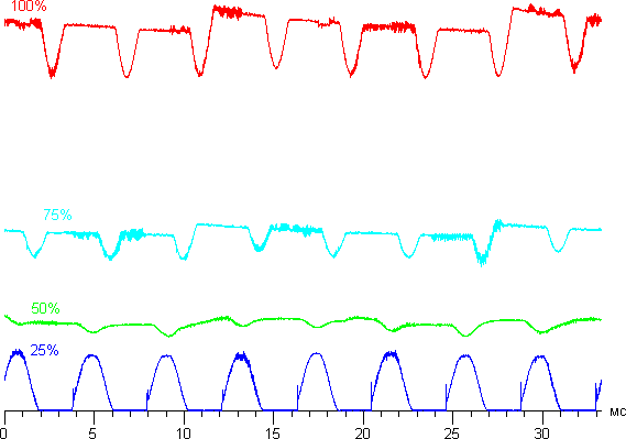
Up to the 50% level there is no flicker; further reduction in brightness is achieved by flickering at a frequency of 240 Hz. This was convincingly demonstrated by German reviewers from the site Notebookcheck.net:
How to check screen flickering
Is your phone screen flickering? Even if your eyes do not notice any flicker, its presence or absence can be easily checked at home without any special equipment. It is enough to open a page with a white background on your smartphone (for example, about:blank in the Safari or Chrome browser), place the phone in a dark room, reduce the brightness to minimum and point the camera of another smartphone at the screen. If we see something similar to what is shown in the video below, screen flickering is present:
To determine at what brightness level the screen stops flickering, open the control center and smoothly move the brightness slider. The disappearance of the diagonal stripes means there is no PWM at a given brightness level.


It has been experimentally established that the iPhone X has a minimum flicker-free brightness level of 50%. But if you keep the brightness at this level, then in dark conditions the device will be uncomfortable to use. The goal is to reduce the effective brightness level of the screen, but avoid flickering.
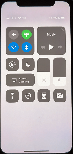
As it turns out, this is quite possible. To do this, there is a special mode in the iOS settings, which can be found in the Accessibility > Display Accomodations settings.


In this mode, the screen is darkened by a software filter. To enable this mode, you need to go to Display Accomodations and activate the slider. Now you need to click on the Display Accomodations inscription and activate the Reduce White Point slider (see screenshot). Try starting with a value between 85 and 100% and adjust to a level that is comfortable for your eyes (the screen brightness in the control center should be at 50%).


Disable PWM in three clicks
So, we were able to activate a software filter that turns off screen flickering at low brightness levels. However, using a phone with the filter always on is inconvenient: in bright light the screen will always be dim.
On the iPhone X, turning the filter on and off can be done by pressing the side button three times, which in previous generations of devices performed the functions of turning the phone on and off. To do this, you need to find the Accessibility Shortcut option in the settings and assign it to enable or disable the Reduce White Point function (see screenshots).


That's all. After activating this feature, we got the iPhone X, whose screen flicker can be quickly turned on and off by pressing the side button three times. Now you can use the device in the dark without fatigue and can quickly turn off the dark filter by pressing the side button three times.
Additional Information
Explanations for the diagram
R2 is a variable resistor with a nominal value of 10K. The central terminal of the resistor is connected through a low-pass filter to the zero channel of the ADC. The voltage across the resistor is converted into a digital code, which is written to the comparison register of timer T0. Thus, using a resistor, the duty cycle of the PWM signal is adjusted.
Led1 is a powerful white LED. The voltage drop across it is about 4 Volts. The maximum LED current is set by resistor R5 and is equal to 100 mA.
(Upit – Uled)/R5 = (5 - 4)/10 = 100 mA
IRLU024N – N-channel field-effect transistor. Instead, you can use any field-effect transistors of the IRL series (L - this means that they are controlled by a logical level)
R3 is a current limiting resistor just in case. R4 – pull-down resistor. The gate of a field-effect transistor cannot be left “dangling in the air.”
Program
//************************************************************
// Training course. Programming AVR microcontrollers in C
// Control the load using
// pulse width modulation (PWM, PWM)
#include
#include
int main( void)
{
//initialize ports
PORTB = 0;
DDRB = 0xff;
//initialize timer T0
TIMSK = 0;
//dir. - fast pwm, output OC0 - non-inverted. shim, clk/64
TCCR0 = (1<
OCR0 = 0;
//ion - supply voltage, left alignment, zero channel
ADMUX = (0<
ADCSRA = (1<
SFIOR = 0;
__enable_interrupt
();
while
(1);
return
0;
}
//********************************
//ADC interrupt
#pragma vector=ADC_vect
__interruptvoid
adc_my( void)
{
//read the high register of the ADC and
//write to comparison register
Explanations for the code
Operation logic
Initialization of peripherals - timer T0, ADC module. Enable interrupts. Endless cycle. In the ADC interrupt, the voltage read from the variable resistor is written to the comparison register OCR0. In the AVR microcontroller, a buffer is organized for this register, and in fact, writing occurs first in it. From the buffer, the value is rewritten to OCR0 only when the TCNT0 counter register overflows. In parallel with the while loop and the ADC module, timer T0 runs and generates a PWM signal at pin OC0(PB2). When the count register TCNT0 overflows, OC0 is set to 1, when the value of the count register matches the comparison register OCR0, the output is set to 0.
Timer initialization
Timer interrupts are not used, so the TIMSK register = 0.
The configuration register TCCR0 is responsible for setting the T0 timer.
Bits WGM01, WHM00 determine the operating mode. 11 - Fast PWM mode.
Bits CS02, CS01, CS00 - set the timer prescaler coefficient. 011 - corresponds to prescaler 64. Timer/counter clock frequency will be Fcpu/64
Bits COM01, COM00 determine the behavior of the OC0 pin. 10 - corresponds to a non-inverted PWM signal. 1 - when TCNT0 overflows, 0 - when TCNT0 coincides with OCR0.
Initializing the ADC
Example No. 2. Generating a sine wave using PWM

Explanation of the diagram
I simply forgot to remove resistor R2 from the circuit. R3 and C8 integrator.
Program
//************************************************************
// Generate sine using
// pulse width modulation (PWM, PWM)
//************************************************************
#include
#include
#include "TableSin.h"
int main( void
)
{
//initialize ports
PORTB = 0;
DDRB = 0xff;
TIMSK = (1<
TCCR0 = (1<
TCNT0 = 0;
OCR0 = 0;
__enable_interrupt
();
while
(1);
return 0;
}
//**********************************************************
//Interrupt timer/counter T0
#pragma vector = TIMER0_COMP_vect
__interruptvoid Timer0CompVect( void)
Often users of the Windows 7 operating system encounter a problem screen brightness settings. To fix this problem, we will look at all the available ways to adjust the display brightness in Windows 7. Adjusting the screen backlight is a fairly simple process that even a novice user can handle. After familiarizing yourself with the material, you will be able adjust the brightness yourself laptop or desktop computer.
Adjusting brightness using standard Windows 7 tools
To set the brightness of a laptop or all-in-one PC using standard 7 tools, first of all you should go to Control panels. You can go to the Control Panel through the menu " Start"or type in the program " Execute» control command
After launch Control panels you need to go to the "" section.

You can now increase or decrease the screen backlight. To do this, set the slider " Screen brightness» to a position that matches your monitor backlight preferences.

You can also go to settings power plan and exhibit brightness, in which the laptop will operate on battery power or mains power.

Changing screen lighting settings using the video card driver
Another interesting way to change the display lighting is to adjust it using video card drivers. For our example, we will consider a driver from the company Nvidia. To open the video card driver settings, you need to right-click on an empty space on the Desktop. A context menu should appear.
In this menu, select the item “ NVIDIA Control Panel"(this may be different for another video card), after which the video card driver settings panel will open.

Now in this panel you need to go to the menu “ Video\Adjust color settings for video».

In the color adjustment menu, go to the “ 2. How to make color adjustments" and set the switch " With NVIDIA settings" By selecting these parameters, you will be able to adjust four properties, including display brightness. To increase or decrease the brightness of the display, drag the slider towards plus or minus and you will see how the screen backlight changes.
Video card manufacturers also have such programs that regulate screen lighting using the video adapter driver. Intel And AMD.
Also on the Internet you can find many programs that adjust the display backlight. All such programs work by accessing the video adapter driver. That is, in essence, they do what you can do in the control panel of the video card (in our case Nvidia). The most interesting of all such programs is F.lux. Its main feature is automatic adjustment of display backlight, which depends on the time of day.
An example of adjusting the laptop backlight using the Fn key
For example, we will use a Lenovo s110 netbook with the Windows 7 operating system.
It uses the Fn modifier key in combination with the ← and → cursor keys to adjust the backlight. To increase the backlight of the Lenovo s110 laptop, you need to use the key combination Fn + →. To lower the backlight you need to use the combination Fn + ←.
 As you raise or lower the backlight, you will see how the value of the graphic indicator changes. The program is responsible for this indicator Hotkey Features.

As you can see, increase or decrease the laptop screen lighting settings using the " Fn", quite simply. You can use this example on other laptops, since the principles of using modifier keys are the same.
Particularly on laptops SAMSUNG NP350 keyboard shortcuts:
- to increase brightness - Fn + F3;
- to decrease - Fn + F2.
Manually adjusting the monitor backlight
For desktop computer users, screen lighting settings can be adjusted on the display itself. For example, we will use a monitor LG Flatron W1943SS. To adjust the lighting, you need to go to its menu. To do this, press the MENU key on the monitor control panel.

After this, press the AUTO/SET key. A brightness adjustment window should open where you can change it.

I would also like to note that the monitor settings do not depend on what OS or driver is installed. They are regulated exclusively in the monitor. Each monitor from a different manufacturer has its own manual settings options. You can find out the details of adjusting the screen lighting parameters of a particular monitor in the manual, which is included with the sale or can be downloaded in electronic form on the manufacturer’s website.
Let's sum it up
This material shows that even a novice PC user can increase and decrease the brightness of the display in Windows 7. And we hope that our material will help you learn how to change the brightness of your computer monitor.
Video on the topic